


It’s true – I love DACs. There’s something awesome about the role they play, translating information from one paradigm over to another form. Sure, you can pick up a precision DAC chip with serial interface for a little over a buck, but building a barebones version from a handful of resistors is a pretty dang sweet trick. If you’ve never built one, I do recommend it. Doing so has a way of demystifying all sorts of related circuits and processes.
Worth noting: If you’re looking for precision, you’re best off sticking with premade DAC ICs. Resistor tolerance alone can have a massive influence on an R-2R DACs output. Adding an op amp configured as a voltage follower will also do wonders for stability.
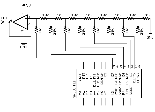
Update: As promised, here’s the schematic for buffering the R-2R DAC – quite simple, actually:

Why do we need a buffer, you ask? Well without proper protection, any device connected directly to the resistor DAC will effectively act like another resistor and therefore distort our DAC’s output. By using an operational amplifier configured as a voltage follower, we recreate the resistor ladder’s output voltage while keeping it free from outside influence.
Do note that the op amp buffer in the schematic is powered by a voltage level higher than our DAC’s maximum output – this ensures we have enough headroom to accurately recreate voltages approaching and including 5V. For more helpful info on the topic be sure to check out Ikalogic’s page on the subject.
Subscribe to the MAKE Podcast in iTunes, download the m4v video directly, or watch it on YouTube and Vimeo.
23 thoughts on “Collin’s Lab: Digital to Analog Converter”
Comments are closed.
ADVERTISEMENT
Join Make: Community Today


As always, another excellent video Collin!
:)
Bravo, Collin. This is so beautifully done (love the drawings and animations) and the info is crystal clear. Nice work.
I tried this schematic with the opamp on the proteus simulator… without the opamp it works great but with the opamp if you giving a voltage < 1v it will be 0.99v
so what is this?
thx
This may be due to the op-amp you’ve chosen. You’ll need to select a “rail-to-rail” op-amp, i.e. one that can swing its output all the way from one supply rail to the other. Not all op-amps can do this, particularly older designs.
I’ve gotten it to work with a single supply LM358.
Great work! Thanks!
can we get a copy of that “demo” code??
the above schematic looks different than the one in the video. the far right node near the arduino pin 2 (“D0/RX”) doesn’t have reference to the ground. is that becuase you supply the opamp in the circuit? what happens if you put another 2R on the system that would make R15 and R1 a Node with a new 2R to ground?
ah – apologies, I’ve corrected and replaced the schematic
It’s a very old invention.
The circuit was marketed around 1986 by Covox, Inc of Eugene, Oregon, for about 70 USD[1] (79.95 USD as of 1989[2]), but as its parts were orders of magnitude cheaper than the complete plug, and as its design was fairly simple, people soon started to build their own variants. The plug was used long into the 1990s, as sound cards were still very expensive at that time. The plug was also quite popular in the demoscene.©http://en.wikipedia.org/wiki/Covox_Speech_Thing
Guys i wonder if anyone can help me… im planning on building a dmx light board to analog 0-10v converter and after viewing this video this looks like the thing i need… has anyone got any ideas of what would be the best way of going about this as i plan to usea picaxe14m2 microchip
Thanks Elliott
How about posting the Arduino sample code for the sine wave !?