


Last Wednesday I spent most of the morning and part of the afternoon chasing a signal anomaly that, as it turns out, did not exist. I wouldn’t call the experience a waste of time, but the experience occupied more of my time than I would have liked. I described the account over at ToolGuyd (An Oscilloscope, an Arduino Servo PWM Signal, and a Wild-Goose Chase) if you’re interested in the whole story.
The result – a better fundamental understanding of Arduino’s servo library, which I will try to share with you with this post. This might seem like beginner stuff, but until last week’s complications I have used Arduino’s servo library quite a few times with ease and assumed proficiency.
Arduino ServoWrite
Arduino’s servo library makes it easier to control servos with minimal code and complications. Arduino’s reference page for the ServoWrite command, which draws upon the servo library, offers the following example code:
#include <Servo.h>

Servo myservo;

void setup()
{
  myservo.attach(9);
  myservo.write(90);  // set servo to mid-point
}

void loop() {}
This sample code instructs a servo, connected to pin 9, to move to its center (90°) position. For a continuous-rotation servo, this will halt the servo’s motion.
In practice, attached servos will adjust to their center positions, but perhaps not exactly.
90° vs. 1500 Microseconds
Most common servos accept inputs from 1000 µs to 2000 µs, with 1500 µs corresponding to the center position. For a 0-180° servo, this would be 90°.
Previously, I had used the servo library with the writeMicroseconds command, which defines the exact pulse width that you want to be sent to a servo. Last Wednesday, my troubles all began when I instead used the write command with a parameter of 90°.
In theory, a write command that instructs a servo to adjust to 90° should send the same pulses as a writeMicroseconds command that sends 1500 µs pulses. That is, write(90) and writeMicroseconds(1500) should both send 1500 µs pulses. But as it turns out, this assumption can lead to problems.
I uploaded the following code to my Uno, and analyzed the signals with an oscilloscope.
#include <Servo.h>
Servo servo1;
Servo servo2;
Servo servo3;
void setup()
{
 servo1.attach(3);
 servo2.attach(4);
 servo3.attach(5, 1000, 2000);

 servo1.write(90); // set servo to mid-point (90°)
 servo2.writeMicroseconds(1500);
 servo3.write(90); // set servo to mid-point (90°)
}
void loop() {}
Here is what the outputs of pins 3, 4, and 5 looked like, from top to bottom:
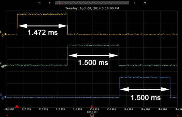
- Pin 3, sent to 90°: 1.472 ms
- Pin 4, sent a 1500 µs pulse: 1.500 ms
- Pin 5, sent to 90°: 1.500 ms
The pulse widths were measured using the oscilloscope’s built-in software, but manual measurements were in agreement.
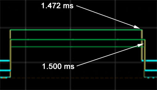
The difference between 1472 µs and 1500 µs is very small, and might not even be enough to make a difference in servo position. Here is a screen capture of the digital pulses, with measurements shown on the bottom right.
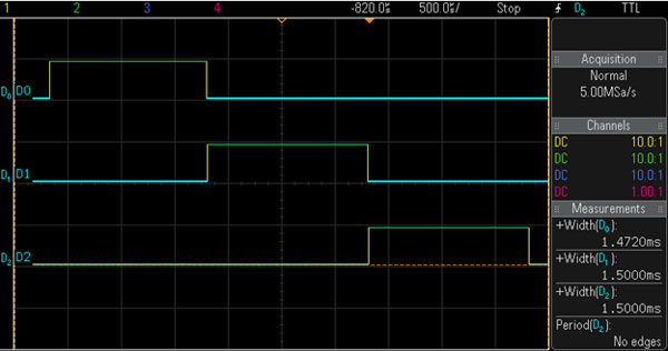
But, it’s still a measurable difference:
If you look at the signal for servo3, which also directs the servo to move to its 90° position, you should see that the pulse width is 1500 µs, the same as for servo2, for which the pulse is designated to be 1500 µs.
The command, write(90), is the same for the first and third servo signals, so why does one send 1.472 ms pulses and the other 1.500 ms ones?
Arduino ServoAttach
The answer lies with the ServoAttach command. The Arduino’s reference page lists two forms of the command:
servo.attach(pin)
servo.attach(pin, min, max)
The first version is the minimal code a sketch needs to designate an i/o pin for servo control. The second includes two very important but optional parameters that designate the minimum and maximum pulse width ranges for the sketch.
In both the attach command’s reference page and the servo library itself, it clearly states that the default min and max settings are 544 and 2400 µs, respectively.
“Optional” Pulse Width Limits
If, like me, you are used to using the writeMicroseconds command instead of write, then you might not have given much thought to the minimum and maximum pulse width parameters. But if you use the write command and set servo positions with angles and degrees, then consider explicitly defining these parameters in your Arduino sketches.
Looking again at my example code, for the third servo signal I overrode the default pulse width limits with 1000 and 2000 µs. This is why the first and third servo signals sent different pulses using identical commands.
servo3.attach(5, 1000, 2000);
Besides the potential for slightly off-center signals, a servo might not predictably interpret pulse widths above or below the limits it was designed for. Under- and over-limit pulses also have the potential to damage a servo.
If a 0-180° servo is designed to respond to 1000-2000 µs pulses, it interprets 1000 µs as “0°” and 2000 µs as “180°.” But, with default pulse width limits range of 544-2400 µs, the Arduino will send a signal of ~1000 µs for an angle of 44°. Sweeping from 1000 to 2000 µs would then only translate to a ~90° swing of the servo arm instead of a full 180°. This, and other potential issues can be avoided if microseconds are used instead of angles in degrees, or if the optional pulse width floor and ceiling parameters are defined in pin setup for each servo.
While I feel somewhat foolish about spending a few hours trying to decipher an unexpected 1.472 ms signal and sort out whether my new oscilloscope was defective, I have a feeling I’m not the only one who takes Arduino libraries for granted. I probably looked at the code a while back, but after using it with predictable results for a while, I simply forgot that it’s not a magical black box that makes servos simpler to control. A look at either the library or Arduino’s page for the attach command would have save me some trouble, but I didn’t think to do either.
The next time your servos act unpredictably in a new project, double check that you set pulse width limits in the pin setup. It might just be that simple.
Stuart Deutsch writes more about tools and workshop topics over at ToolGuyd.
0 thoughts on “Arduino’s Servo Library: Angles, Microseconds, and “Optional” Command Parameters”
ADVERTISEMENT
Join Make: Community Today


solved mine problem too
thanks man!