


Yesterday just under two thousand MicroView boards shipped without a bootloader, two of them were mine. Along with pretty much everyone else I’ve been seriously impressed with the response by Geek Ammo—the company behind the MicroView—and by SparkFun—who are manufacturing it—to the problem.
A lot of Kickstarter projects would give you some instructions on how to flash the bootloader onto the board, and you would consider yourself lucky if the instructions were good enough to get the job done. Here the companies involved are going well beyond that.
Everyone makes mistakes, but it’s how you handle them that makes the difference, and both companies are handling this problem with honesty and total transparency. You can’t ask for more than that.
Their response is especially impressive considering that it’s turned out to be fairly easy to fix things yourself. While my initial impression yesterday was that the MicroView wasn’t going to come apart, or at least not in a way that would let you put it back together again, it turned out to be fairly easy to crack the case of the board without breaking it, and if you can get it apart you should be able to upload a bootloader.
It was game time…
Opening the MicroView


The MicroView is actually fairly easy to open. You’ll need to insert a thin metal tool between the edge of the glass top and the plastic surround—I used a metal spudger but a razor blade or a very thin precision screw driver would probably do—and carefully lever the glass upwards.
After removing the glass you’ll see the OLED display, you’ll similarly need to pry this upwards. Here I used a plastic opening tool, as I figured something non-conductive was needed, but again anything thin enough to hook behind the display will do. Be careful however as the display is attached to the PCB using a ribbon cable, and prying it too far foward might dislodge, or even break, this cable.
Building an AVR Programmer
To upload the bootloader to the MicroView you’ll need an AVR Programmer. Don’t worry if you don’t have one of these, you can easily use an Arduino board to build one.
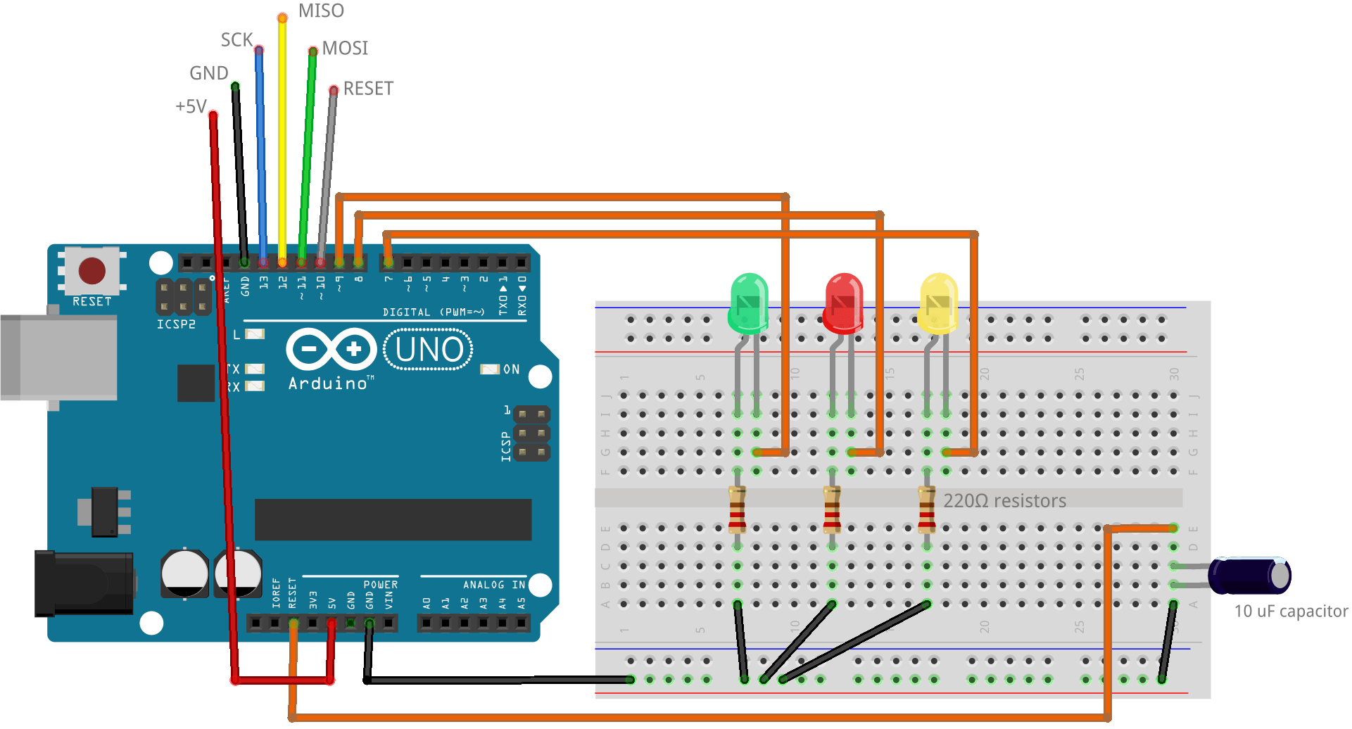
Go ahead and wire your Arduino board as shown in the diagram above. The 10 uF capacitor inline between the reset and ground pins is needed when using an Arduino Uno or Leonardo, however do not add this until after you upload the ArduinoISP sketch to the board—you’ll find the sketch in the Examples menu of the Arduino IDE—as with this in place sketch upload won’t work correctly.

After uploading the sketch, and wiring in the capacitor, you should see that the left-most LED which is green in the above diagram, and connected to 9 of the Arduino, is softly pulsing—this is the heartbeat LED telling you that the programmer is running. The other two LEDs are for when the programmer is active. The middle LED, which is red in the diagram and attached to pin 8 of the Arduino, lights up when something goes wrong—hopefully we shouldn’t see that at all—while the right-most LED connected to pin 7 of the Arduino will light up when the programmer is active and talking to the “slave” board which we’re programming.
Connecting the Programmer to the MicroView


Because of its small size the MicroView doesn’t have a standard ICSP header connecter. However wiring the programmer to the MicroView isn’t too difficult. Three of the wires can be directly connected to the external pins of the MicroView, so it’s only the MOSI, MISO and SCK that need to be connected to those small internal vias.
| Wire | Arduino Pin | MicroView Pin |
|---|---|---|
| +5V | +5V | 16 (Vin) |
| GND | GND | 8 (GND) |
| MOSI | 11 | 11 (interior via) |
| MISO | 12 | 12 (interior via) |
| SCK | 13 | 13 (interior via) |
| RESET | 10 | 1 (RST) |
The wiring connections between the Arduino and MicroView
I found that it was fairly easy to load a little solder onto the vias, and then by heating the end of the connecting wires while touching them to the blob of solder on the via, they could be tacked lightly into place. You don’t want to use too much solder here as, once the bootloader has been loaded onto the board, we’ll be removing the wires and resealing the case.
Uploading the Bootloader


Go ahead and plug everything together. Once the assembled and plugged in the heartbeat LED on the programmer should start pulsing and the MicroView should boot as normal into the pre-loaded demo sketch. We’re ready to go.
Sparkfun has made a custom bootloader hex file available—go ahead and download it—this is what we’re going to load onto the MicroView. Then you have to locate your copy of avrdude—you’ll find it inside your Arduino IDE in the hardware/tools/var/bin directory, although on OS X this is actually buried inside the Arduino application bundle.
Now all you need is the name of the serial port that your Arduino board is using—you can grab this from the Tools→Ports menu of the Arduino IDE—and you’re good to go. Whilst in the directory that avrdude is located enter the following command,
./avrdude -C ../etc/avrdude.conf -P /dev/tty.usbmodem1411 -b 19200 -c avrisp -p m328p -v -e -U flash:w:/Users/aa/Downloads/MicroView_combined_8-19-14.hex -U lock:w:0x0F:m
substituting the name of your serial port, mine was /dev/tty.usbmodem1411, and the path to the MicroView’s bootloader—mine had ended up in my Downloads folder.

As soon as you initiate the upload the screen of the MicroView will go blank, and while uploading to the right-most LED should light up. If the middle LED lights up, you’ve got a problem—take a look at the output from avrdude, it’s usually fairly self-explanatory, and try again (check that you’ve got all your path names and serial port names correct when invoking the command).
However if everything goes well, the right-most LED will go out and the MicroView will reboot and start running the demo sketch again. Congratulations! You should now have a working MicroView which will allow you to upload code.
Uploading Code
The MicroView Blink sketch running on a fixed MicroView
We can test whether we have a working MicroView without closing the case back up. Go ahead and put detach the MicroView from the programmer—you can leave the three jumpered wires connected to the internal vias—and attach it to its USB Programmer.
Then in the Arduino IDE and open up the MicroView Blink sketch—this sketch will draw a circle for one second, then off for one second, repeatedly—you can find it in the Examples→MicroView→LearningKit menu.

You should now be able to follow Geek Ammo’s normal getting started instructions and upload the sketch to the MicroView. If all goes well you should see the promised circle blinking on and off on the OLED screen.
Closing the MicroView


Now you know everything is working, you can go ahead and un-tack those three jumper wires using your soldering iron. Just a second or so of heat, and a brief tug, should pull them off the board so long as you didn’t use too much solder.
Once that’s done gently fold the screen back into the case—you should be able to use your fingertip. The screen should just pop back into place, and once it’s back the glass top of the MicroView should likewise just snap back into the case. However before doing that you should carefully wipe the glass down with a cleaning cloth as dust specks underneath the glass will be very obvious against the OLED screen, and probably pretty irritating.
Summary

That’s it, we’re done, and you now have a fully working MicroView board. Possibly with a couple of scratches, but more or less intact. Congratulations!
12 thoughts on “How to Fix Your Broken MicroView”
Comments are closed.
ADVERTISEMENT
Join Make: Community Today


[…] Read more on MAKE […]
[…] (21/Aug): A walkthrough of how to fix the […]
[…] Read more on MAKE […]
Excellent post. Many thanks to all concerned and Sparkfun are to be commended for their speedy response and excellent customer service. We all make mistakes but not many are as helpful, open and gracious as Sparkfun have been.
Perfect! Thank you!
[…] is good tutorial from Make on how to fix this, but in their write up they are soldering to the via pins, and I didn’t […]
Hi, thanks for the helpful article! I would like to point out one thing: The “The wiring connections between the Arduino and MicroView” illustration has a typo for “MOSO” (the one with yellow background), when it should be “MISO”. I know that this should be the MISO pin but it might cause confusion for others who read your article. Thanks!
Oops! Thanks for catching that, fixed!
Thanks for the walk through! Sorry for the newbie question, but do you
know if we can use the usb “dongle” that comes with the microview to
upload the bootloader? As in this picture:
https://twitter.com/kome_P/status/502307332512940033/photo/1
I wouldn’t have thought so, although I could be mistaken. Possibly the AVR programmer is right-of-frame in the above picture, and the USB Programmer is being used just to load the sketch. Hmm…
Uhhmmm… can’t you send the thing back for a replacement? Well, I guess faulty devices received, can, in certain cases, be a learning experience for those who wish to delve into the guts of said devices. Still, I can say with nearly 100% certainty, if Wal Mart tried to sell it’s electronic products with such a defect and offered this “simple” fix, Wal Mart would soon be selling 0% electronics.
Sparkfun and Geek Ammo are going to replace every single faulty board, https://www.sparkfun.com/news/1575. But they aren’t asking for the broken boards to be returned. That means if you do the fix, you end up with double the number of boards. Also, since you’re going to get a replacement anyway you have nothing to lose.
what syntax should i use on a pc for calling the com port in the avrdude command, just something like “COM3”
Sorry, been years since I used a Windows machine. My guess would be yes, COMx would be the right syntax. But YMMV.
[…] a bootloader? Make interviewed [Marcus Schappi], the guy behind the MicroView. There’s also a tutorial on how to fix the […]
[…] a bootloader? Make interviewed [Marcus Schappi], the guy behind the MicroView. There’s also a tutorial on how to fix the […]
FWIW, the wiring diagram for “Building an AVR Programmer” has the cap completely bypassed and Arduino RESET held low. Yes, the text below explains that the cap should not be installed until the ArduinoISP sketch has been loaded, but this wiring method as shown will trip up newbies.
Everything else looks good, thank you!
I followed the procedure and everything went fine. Avrdude ran with no issues, the default scetch ran but when I upload a new sketch I get the same error, stk_500. Any suggestions as to what the issue might be? Thanks for the article.
I sorted out the problem. Make sure the microview is off the programmer when you flash it.
Sorry for being slightly off-topic. But is it possible to use an arduino to program a microview without the USB-programmer or an FTDI-cable?
Excellent clear post.
Just one suggestion, and it applies to many USA writers: sed -e ‘s/go ahead and//g’ It is totally superfluous. (and it is especially annoying in Youtube vids when it is spoken.)
+1. One or two is sparky and fun, five is excessive. A bit like exclamation marks.
Are the LED diagams backwards? I thought the longer LED was positive?