Traditional photography is fantastic. I love the way mechanical cameras feel in my hand, and I love the way film makes me think about composition and lighting before I actually take a shot. The only thing I don’t like about traditional photography is the cost of having film processed or buying equipment to develop my own.

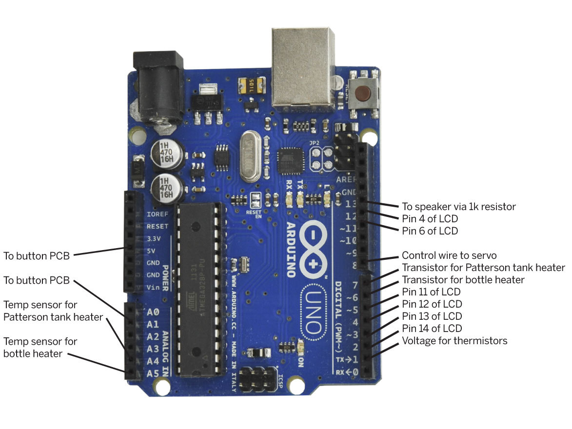
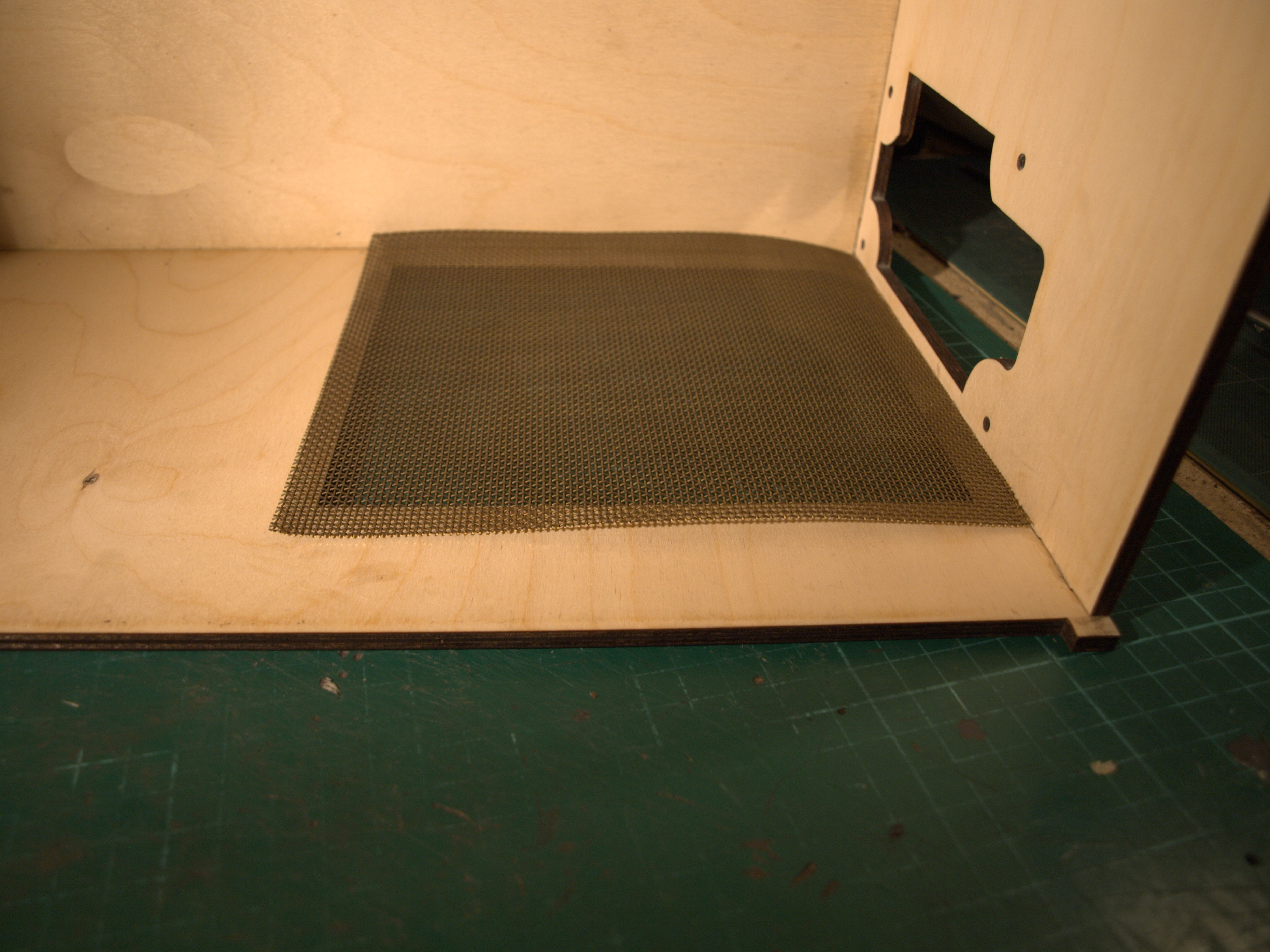
To cut costs and have a little fun with an Arduino along the way, I decided to make my own film processor. The equipment needed to turn a roll of exposed medium-format color film into negatives actually isn’t that complicated, and the chemical process is also straightforward. Using a standard developing tank and chemicals, all you really need are a stable working temperature and accurate timing, which you can accomplish using an Arduino, an LM35 temperature sensor, and a few electrical components.

To develop film, you immerse it in developer at a specific temperature for a specific amount of time, agitate it every few seconds to ensure an even process across the film, then repeat the process with fixer/blix solution, and repeat again with rinse water. This can be done in a Paterson tank, which lets you pour liquids in and out without exposing the film inside to any light. With a film-changing bag to load the film into the tank, you don’t need a darkroom!

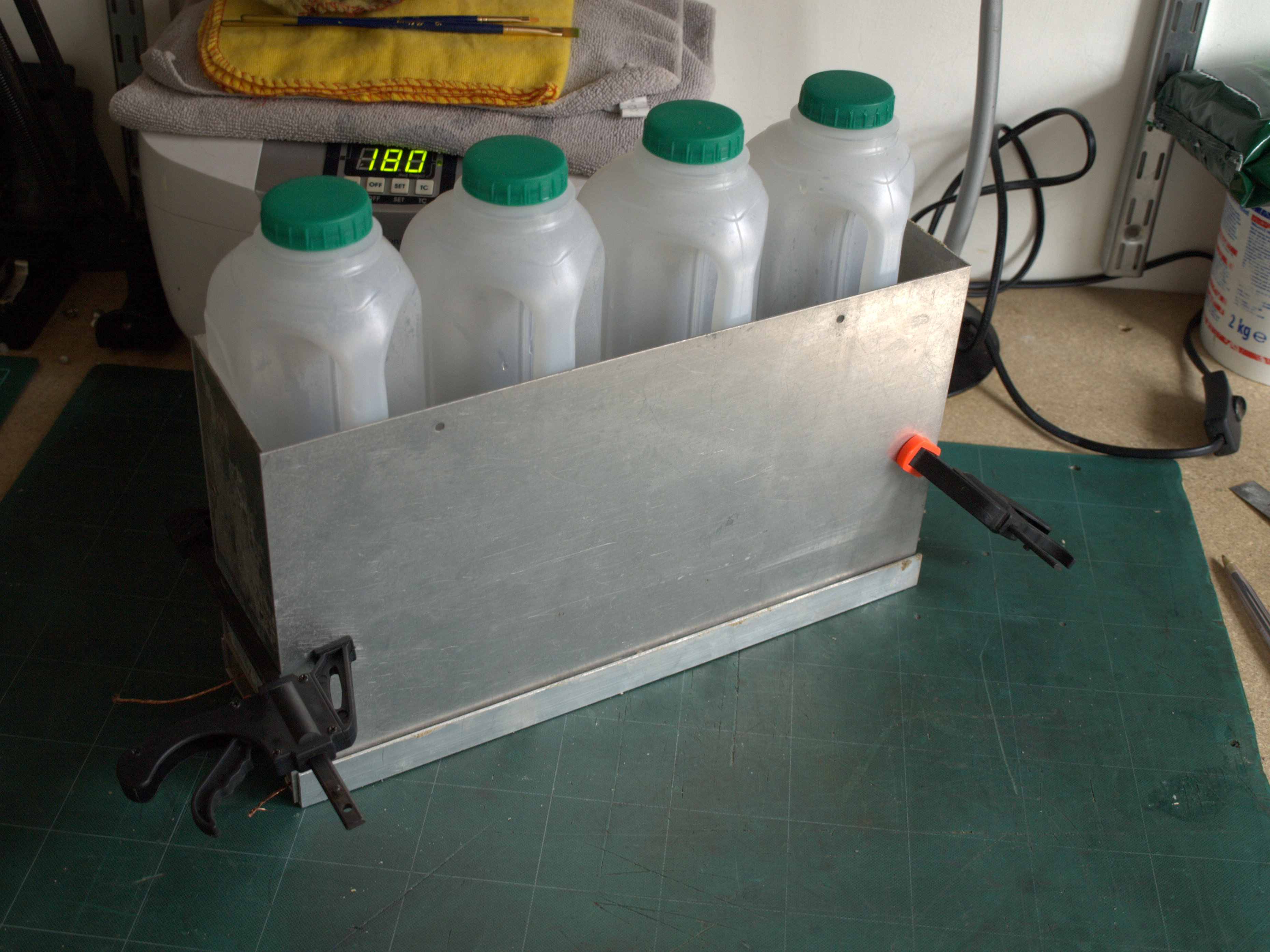
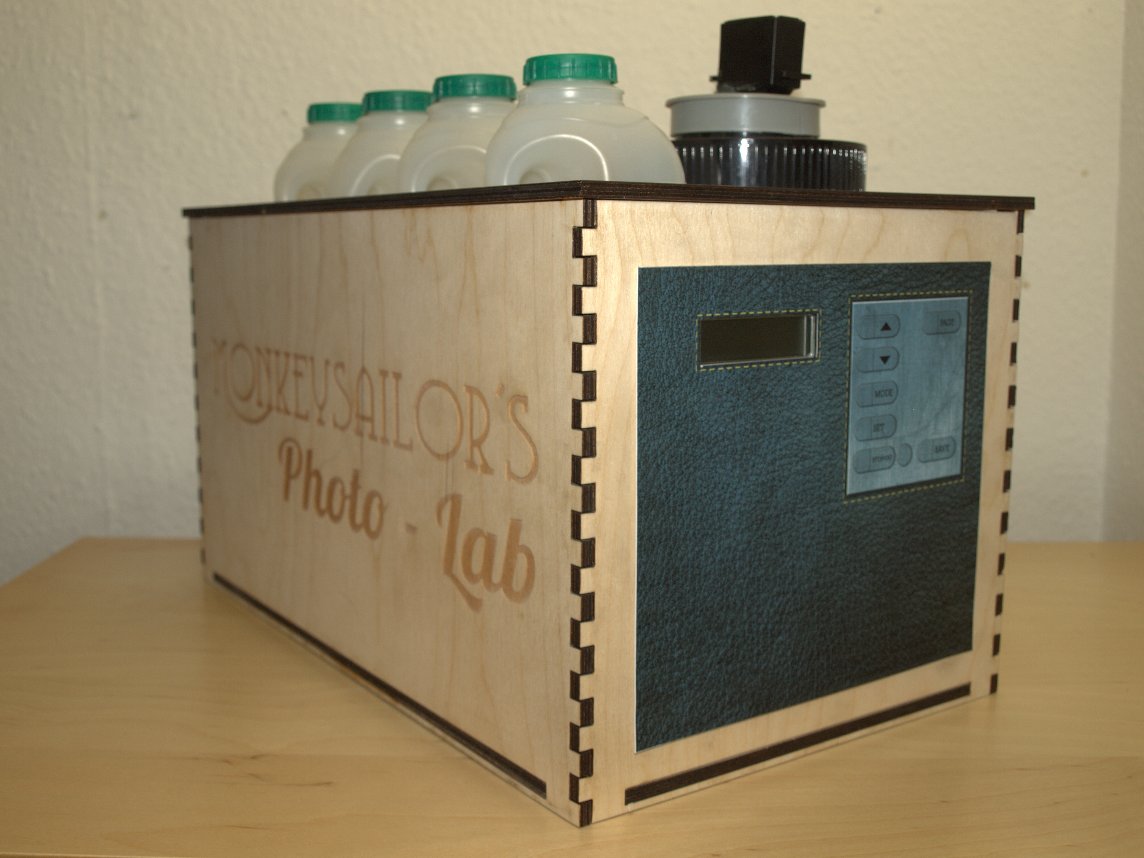
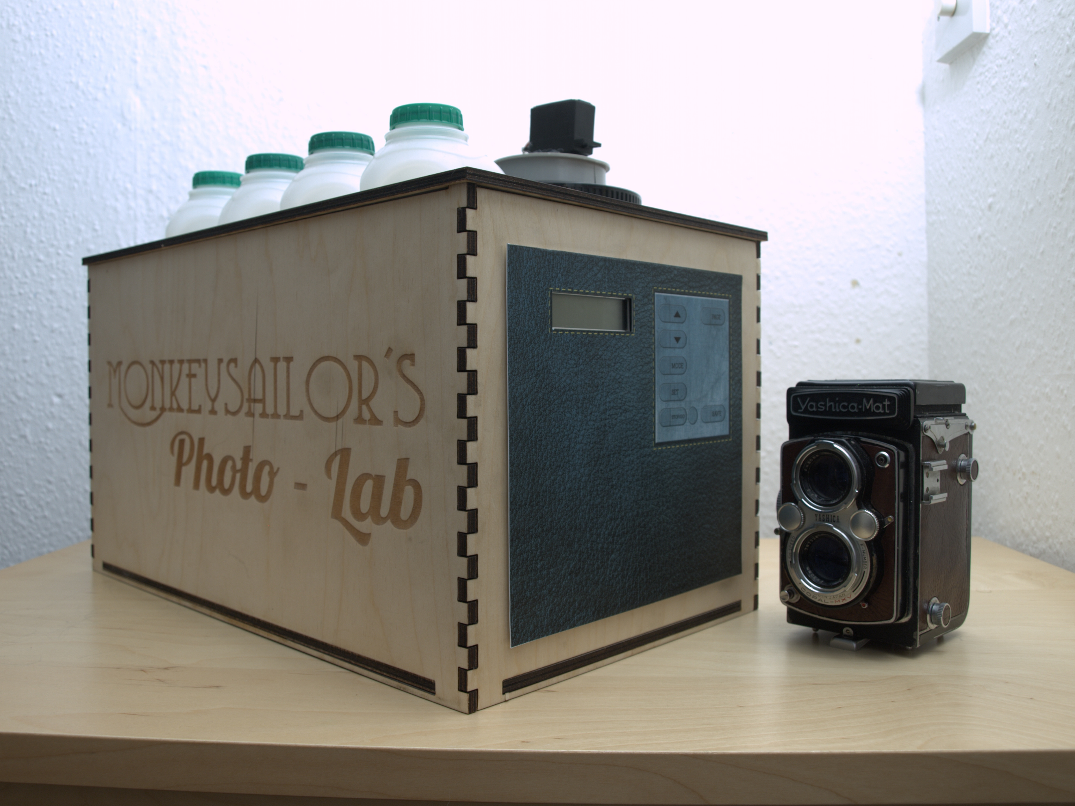
Different film types or chemicals require different times and temperatures, and the brightness, contrast, or color will not develop correctly if they’re wrong. So I needed to work out a system that would maintain and monitor the temperature of 4 chemical bottles, and time the processing down to the second.

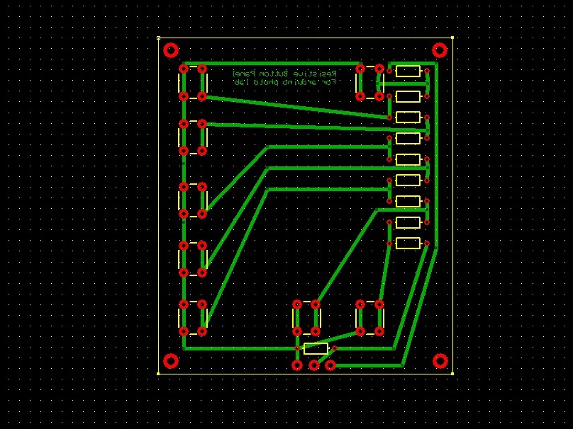
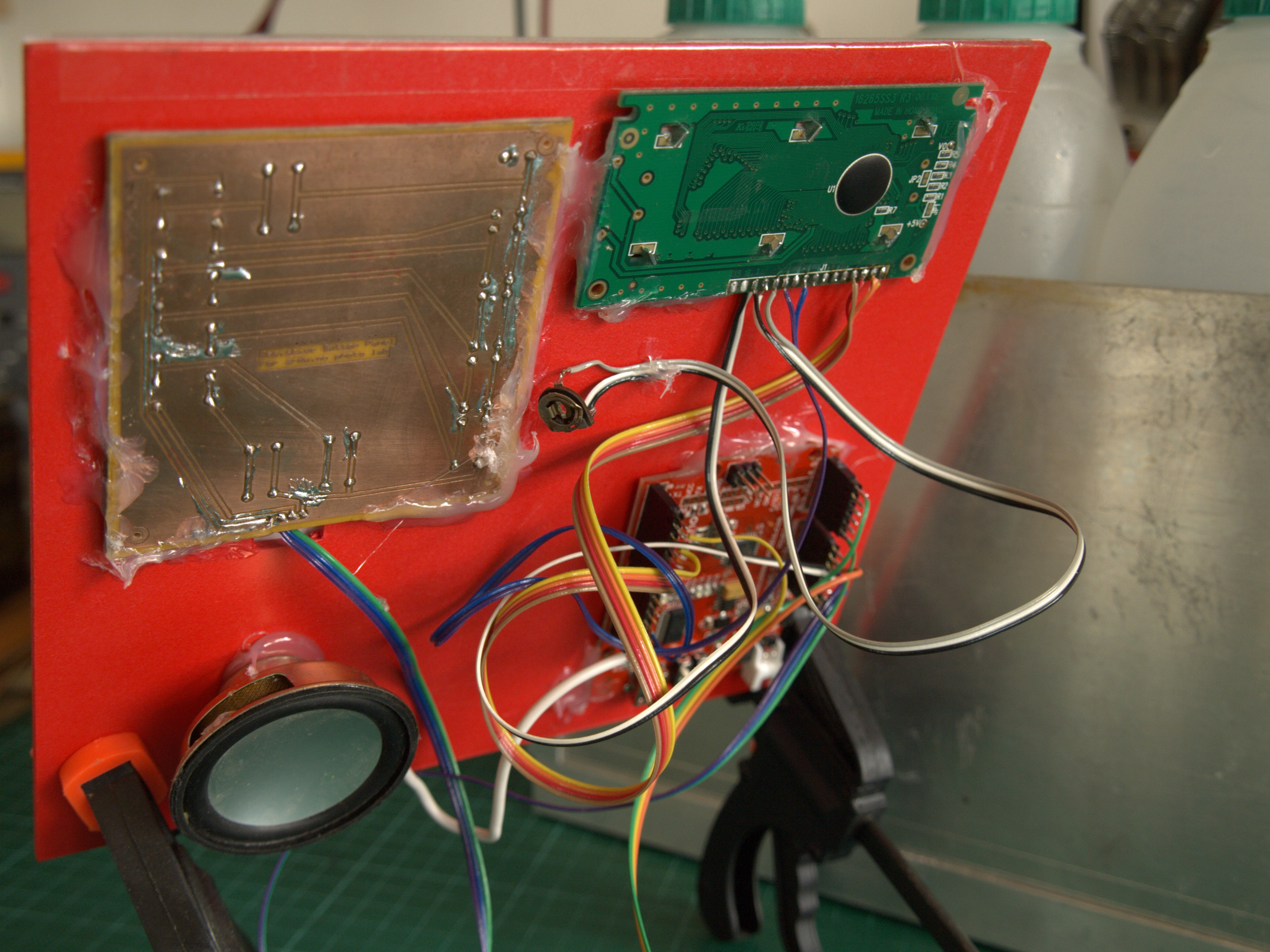
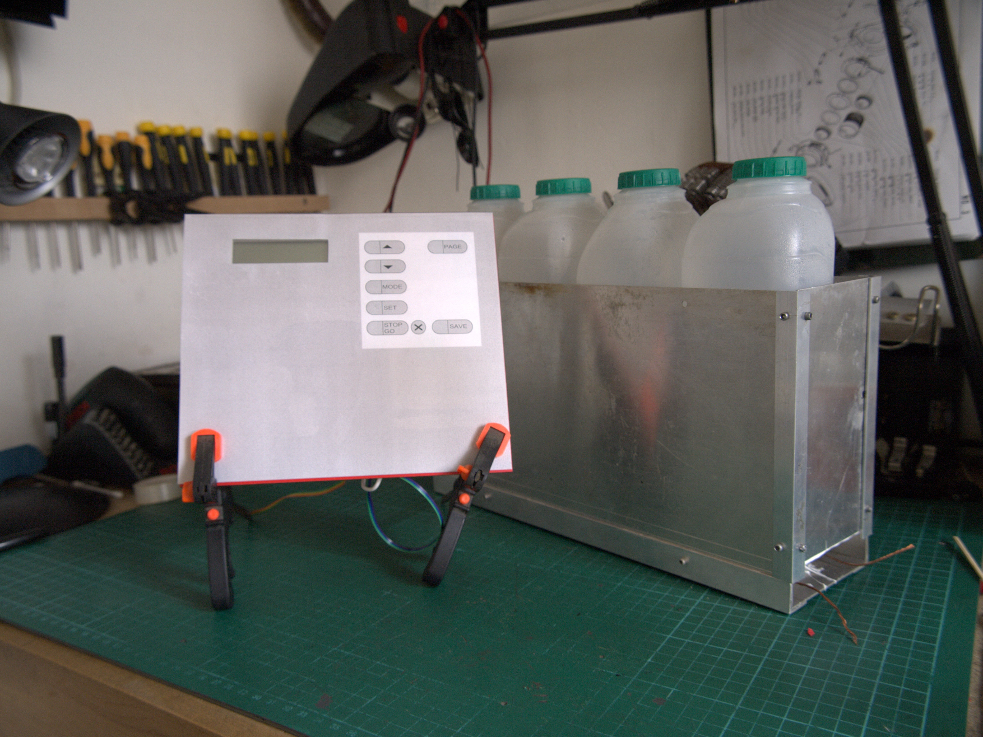
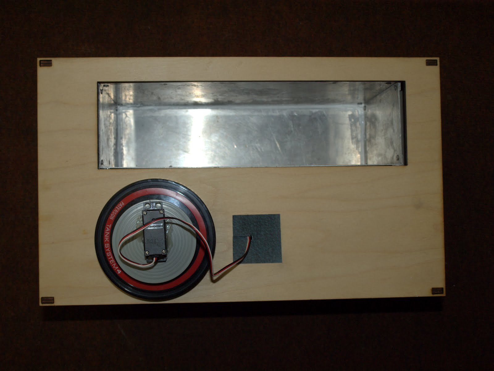
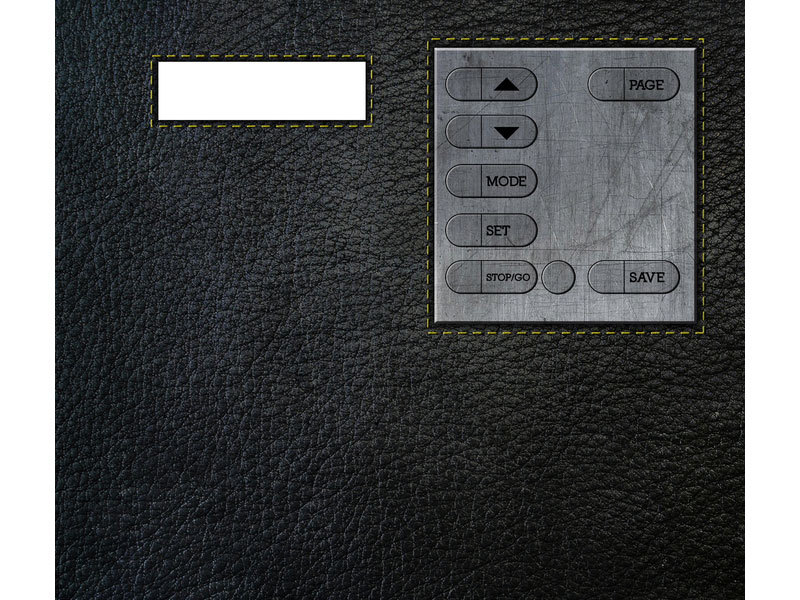
I also thought it would be handy if my Photo Lab could agitate the film automatically, and store my time and temperature settings so I wouldn’t have to reprogram them with each batch. For the auto-agitation, I used a hobby servomotor, and for programming I designed a control panel around a Hitachi HD44780 16×2 LCD display, with pushbuttons for making menu selections. The buttons let you move through the menu screens, increase and decrease heater, timer, and agitation values, and save/restore the settings to the Arduino.

With the agitator, timer, and menu system,the Photo Lab project plans grew larger than my original idea for a chemical warmer, but I was confident I could make it all work. At one point I realized that although I had set my sights on a photographic processor, my system would be great for warming any liquids. With a little modification, it could be used to control hotplates, furnaces, and fish tank heaters for other projects.

Downloads

Download the code, schematics, and templates.

Project Steps

Build the control panel.

Download the code, schematics, and templates.

At first, the Arduino I/O pins seemed out-numbered by the connections needed for the LCD screen, temperature sensors, servo, and pushbuttons.

To get around this problem, I made a custom PCB with all the buttons wired in parallel to a resistor array with different-value resistances along each path. Each button press produces a different voltage through the board, which lets the Arduino read all the buttons from a single analog input pin.

For power, I used a standard ATX power supply unit (PSU) for tower PCs. These provide plenty of amps, have a built-in fan and surge protection circuit, and make available a nice selection of voltages via their 20- or 24-wire cable that connects to the PC motherboard.

To turn the power supply on, you connect its green and black (ground) wires, and then the yellow and red wires supply +12V and +5V, respectively.

I wired my circuitry to the PSU via a cut ATX adapter cable, which saved me from cutting the PSU’s own cable, but you could cut and solder the unit’s wires directly. I connected the Arduino to a 12V line. I could have bypassed the Arduino’s internal voltage regulator and connected it directly to 5V, but felt that it wasn’t necessary.

See the photo for a diagram of the Photo Lab’s microcontroller connections. I glued the button PCB and LCD screen onto a sheet of PVC with holes for the display and buttons. I made a larger aluminum sheet (195mm×175mm) with matching cuts to the front, drilled its corners for screw mounting to the main box, and glued the aluminum onto the PVC.

I chose an LCD display without backlighting to use the Photo Lab in a darkroom, and powered it with 12V from the power supply. Following the LCD’s datasheet, I connected a small potentiometer to control the contrast, and glued it to the back of the pane.

After I connected the LCD and speaker to the Arduino and glued them to the PVC, the interface hardware was complete.

A designer friend came up with a nifty retro design for a panel cover, styled after an old camera, which I printed onto a sheet of plastic film. Aside from making the panel look pretty, this cover acts as a splash guard for the push buttons.

Finally, I made sure everything was glued securely in place, and I uploaded my Arduino sketch to the microcontroller for testing.

Connect the temperature sensors.

Now that I had my panel, I could use it to control and sense things in the real world.

I experimented with thermistors and thermocouples, but decided to use two LM35 solid-state temperature sensors, one for the chemical bottles and one for the developing tank. These sensors are accurate to about 0.5°C, which is good for sensitive color film processing.

I powered them in parallel from the Arduino’s D1 pin, and for greater accuracy, they’re only powered up when they’re about to take a reading. Continuously supplying them with power generates a bit of heat that can throw their readings off.

Mount the servo.

I attached the servomotor to the lid of my developing tank with hot glue, and added a stirrer to the servo shaft using bent wire. To avoid the tank lid being permanently attached to the Photo Lab along with the servo, I added a servo connector to the top, which is wired to the main board’s power, ground, and Arduino pin D8 for control.

Build the bottle warmer.

To make a bottle holder, I measured the 4 bottles that I use to store developing chemicals, and constructed an aluminum box to fit neatly around them. I used thin aluminum sheets, and riveted them to aluminum angles at the corners. The pairs of side pieces measured 90mm×150mm and 320mm×180mm, and the bottom piece measured 90mm×320mm.

For the heating, I wound Nichrome heating wire around a screwdriver to make 4 coils. I connected these in parallel between 2 copper power wires, and sat one under each bottle in the bottom of the aluminum box.

The coils are powered by the 5V line from the PC power supply, switched by a STP36NF06 transistor controlled by Arduino pin D6. Alternative coil winding and voltages will produce different results, so you can tailor the element design to suit your needs.

I wound the heater wire into coils and set into fire cement at the bottom of the box with the power wires sticking out one end. I added another sheet of aluminum to close the bottom of the box, and sealed with silicone.

I mounted the temperature sensor on the bottom of the aluminum box near the wires that lead to the heating element. The sensor connects to Arduino analog pin A5. I did think about suspending it inside one of the bottles, but I felt that having the sensor on the element would be neater.

Build the developing tank warmer.

Paterson developing tanks are cylindrical, so instead of making a holder out of sheet metal, I used an old cigar can that fit it nicely. A large soup can also works.

I drilled a hole in each side of the tin and fitted a Nichrome coil in place with fire cement as I’d done with the bottle warmer.

Finally, I glued the temperature sensor to the tin with epoxy resin. This heater coil is controlled by a transistor connected to Arduino pin D7 and the sensor feeds into pin A4.

Make the case.

The laser-cut Photo Lab case was manufactured from birch-faced plywood by my friends over at Hines Design Labs. I designed the case to accept an ATX power supply, and before I fitted it in, I covered the air intake with wire mesh.

You can see my templates in the zip file from Step 1. You can also add panel artwork like the 3rd image from John Ranford.

Final assembly.

I connected several of the power supply’s 5V (red) lines together so they could handle the current for the heater elements. The power switch for the PSU acts as the power switch for the Photo Lab, and I connected the green and black ATX wires together so that the PSU supplies power as soon as it’s plugged in and turned on.

I fit the aluminum box and cigar can into the project box using a combination of wooden blocks, Meccano brackets, wood screws, and wood glue.

Nothing inside the box should get hotter than 140°F (60°C), so I didn’t make any special effort to protect the wood. As a final measure, I packed some fiberglass thermal insulation around the heaters.

Conclusion

The Big Picture

I’m very pleased with this project, and I now use it to process my rolls of film. The only problem so far is that the heaters take a long time to bring the bottles up to temperature, so I think I might replace the elements with 12V or 240V versions. This should be easy because it involves no modifications beyond exchanging the transistors for solid-state relays.

The timer and auto agitator take all the stress out of processing film, and mean that I don’t have to keep an eye on the clock. I can leave the film to process and trust that the tank will be stirred every few seconds.

The processor is also handy for developing black and white film using weak solutions to achieve finer grain, which is a slow process. Experimental developers such as caffeine (yes, caffeine!) can take more than half an hour to process, and my Photo Lab machine lets me avoid a nasty hand cramp from manually stirring a tank for 30 minutes.

This project first appeared in MAKE Volume 31, page 123.