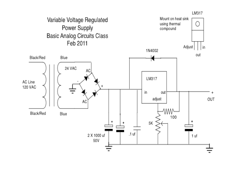
Hobbyist electronics projects need robust, reliable power supplies for prototyping and testing. I learned how to build this circuit from the Basic Analog Circuits class at ITP taught by Eric Rosenthal, but took it several steps further in building a solid enclosure and integrating a voltage meter. Now it lives on my desk, ready to power most small projects I’m working on.

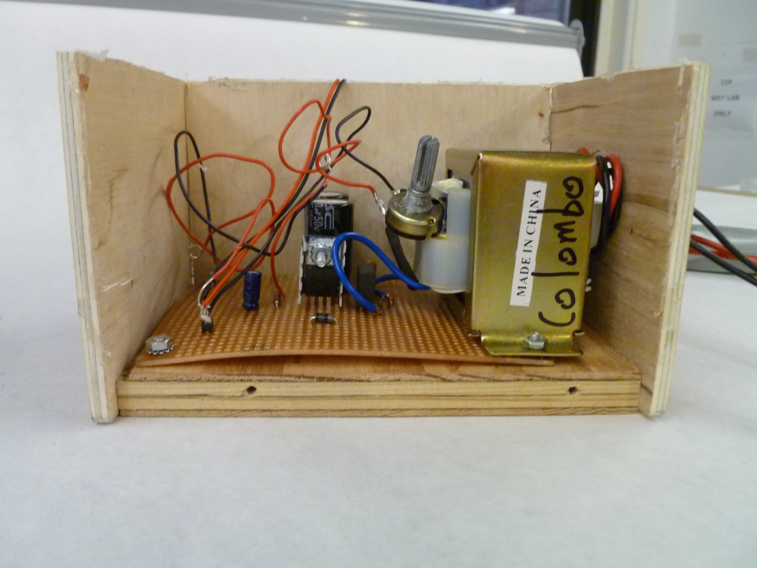
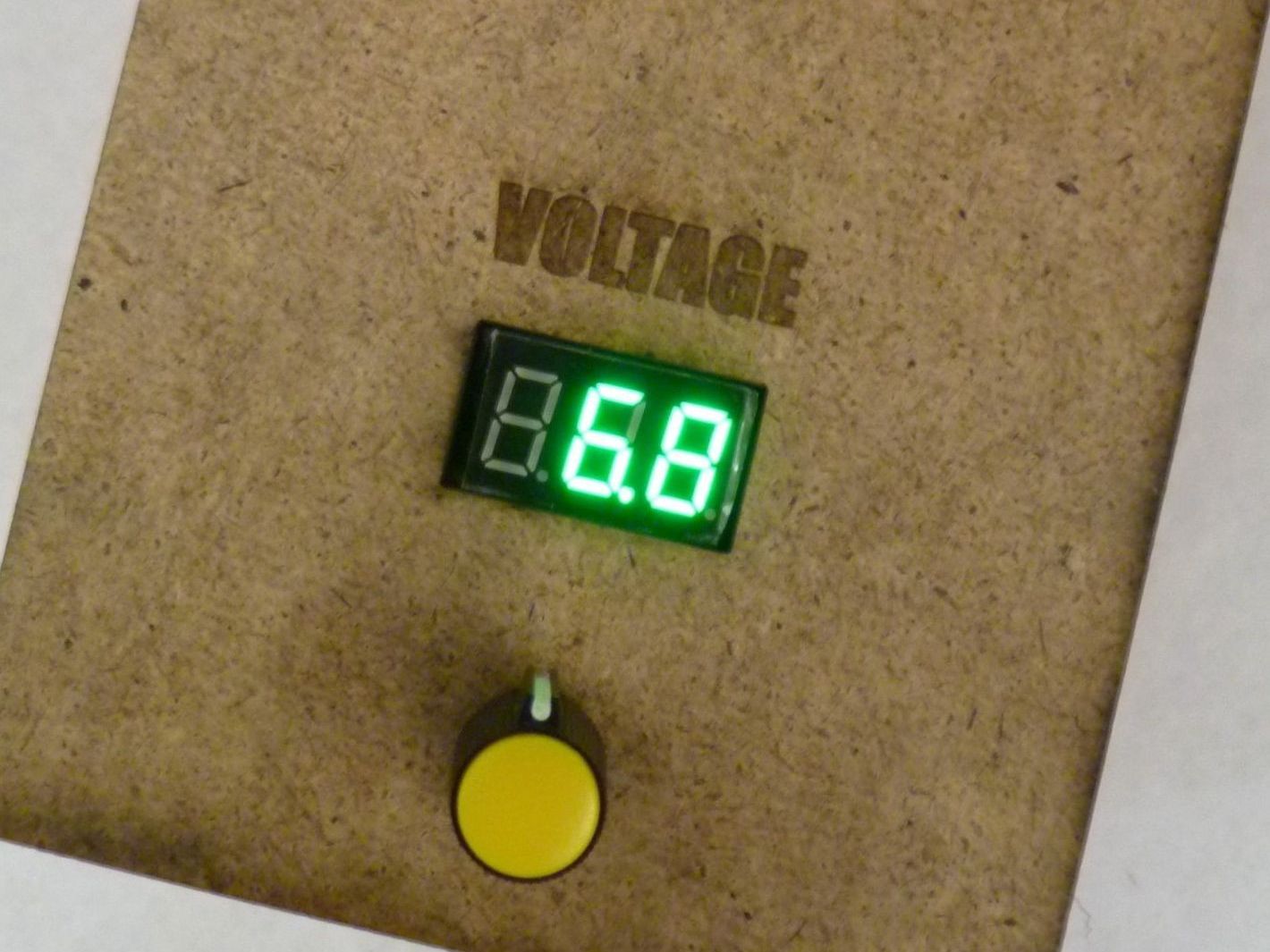
You’ll see example shots of point-to-point wiring of components to perfboard while following a schematic for this power supply. A wood enclosure is built, and Adafruit’s Mini Volt Meter, Vout posts, and a potentiometer are mounted in the final product.

Parts List:

  • One 3×5″ perfboard
  • LM317 variable voltage regulator
  • BR805D Bridge Rectifier
  • Heat Sink
  • 120 VAC to 24 VDC transformer (mine is part number LP-575)
  • Power cable
  • Two 1000 microfarad capacitors
  • One 0.1 microfarad capacitor
  • One 1 microfarad capacitor
  • One 100 ohm resistor
  • One 5k ohm variable resistor
  • One 1N4002 diode
  • 1/2″ plywood
  • 1/8″ wood or MDF
  • six half inch wood screws
  • 8 1/2″ long x 1/8″ wide nuts and bolts
  • Plastic knob
  • Mini volt meter from Adafruit Industries

Project Steps

Solder the positive and negative (red and black) leads from the transformer to the power cable. Twist the threaded wires together and use a liberal amount of solder, completely covering all connections. Finish with heat shrink tubing or electrical tape.

Apply thermal compound to LM317 and screw into heat sink.

Wire all components to the perfboard. There are a couple of ways to go about this: some find it’s easier to put all the components into the holes first and bend the wires so they stay in place, then solder everything together. I like to go step by step, following each part of the schematic individually to verify that I have every connection correct.

You’ll be using point-to-point wiring on the back of the perfboard. Make sure that all your connections are separated, and use insulated wires if you have to cross over any connections you’ve already made.

Make sure to solder leads onto your potentiometer for easy mounting to the enclosure later on. Also be sure to short out the middle pin to an adjacent pin on the pot, so it functions as a variable resistor and not a voltage divider.

Solder long leads to two header pins on your positive and negative output for easy mounting to the enclosure later on.

Solder the mini volt meter directly to the output leads.

Now you should be ready to test your power supply. Remember that you are working with high voltage from the mains. Use all proper precautions when testing, and if you don’t know what those are, find someone who does and can help you!

Be ready to unplug quickly if you see smoke or smell something funny. Usually this might happen because a component is shorted and burned out. It can generally be diagnosed and fixed relatively quickly.

There are many different ways to build wooden boxes for project enclosures. Briefly, I used the thick plywood as a base to drill into, and attached the thinner sidewalls with machine screws after drilling pilot holes. I then hot-glued the sides and top together.

I used a 1″ hole saw to snake the power cable through. This leaves room for the plug to fit through and also aids in ventilation.

Attach the perfboard and transformer to the bottom of the enclosure using nuts and bolts.

Drill holes for your potentiometer and power terminals, and cut a space for your volt meter. I used a laser cutter to do this step, but it can also be done with a drill and a coping saw or scroll saw.

Twist the positive and negative leads to two separate screws. These will serve as your power terminals.

Attach power terminals and potentiometer to the face of the enclosure using nuts.

The mini volt meter comes with mounting holes, but I opted to hot glue it into place. This seemed to secure it well.

Carefully tuck all your wires into the enclosure and hot glue the control panel to the rest of the enclosure.

Attach a knob to your potentiometer.

Make sure you’ve clearly labelled your positive and negative terminals. Now you can easily attach alligator clips to them and use this adjustable power supply for many different types of electronics projects.