This project is part 4 in the building a robot arm tutorial. In the first part I show how to design the arm, the second part shows how to design the base, and the third shows how to design the mount.


robot arm main image

After all of the Computer Aided Drafting (CAD) and 3D modeling in my past articles on making a robot arm (see links above), we are now ready to explore and expand on ways to control the robot arm. There are a number of ways to control the robot arm. The best way to control the stepper motors that actually control the movement of the arm is through a microcontroller. You might already be familiar with some microcontrollers (after all there are a number of excellent options); because steppers motors are relatively simple to use, they can be incorporated into projects driven by Arduino, Raspberry Pi, and even more complex controllers like Beaglebone Black.

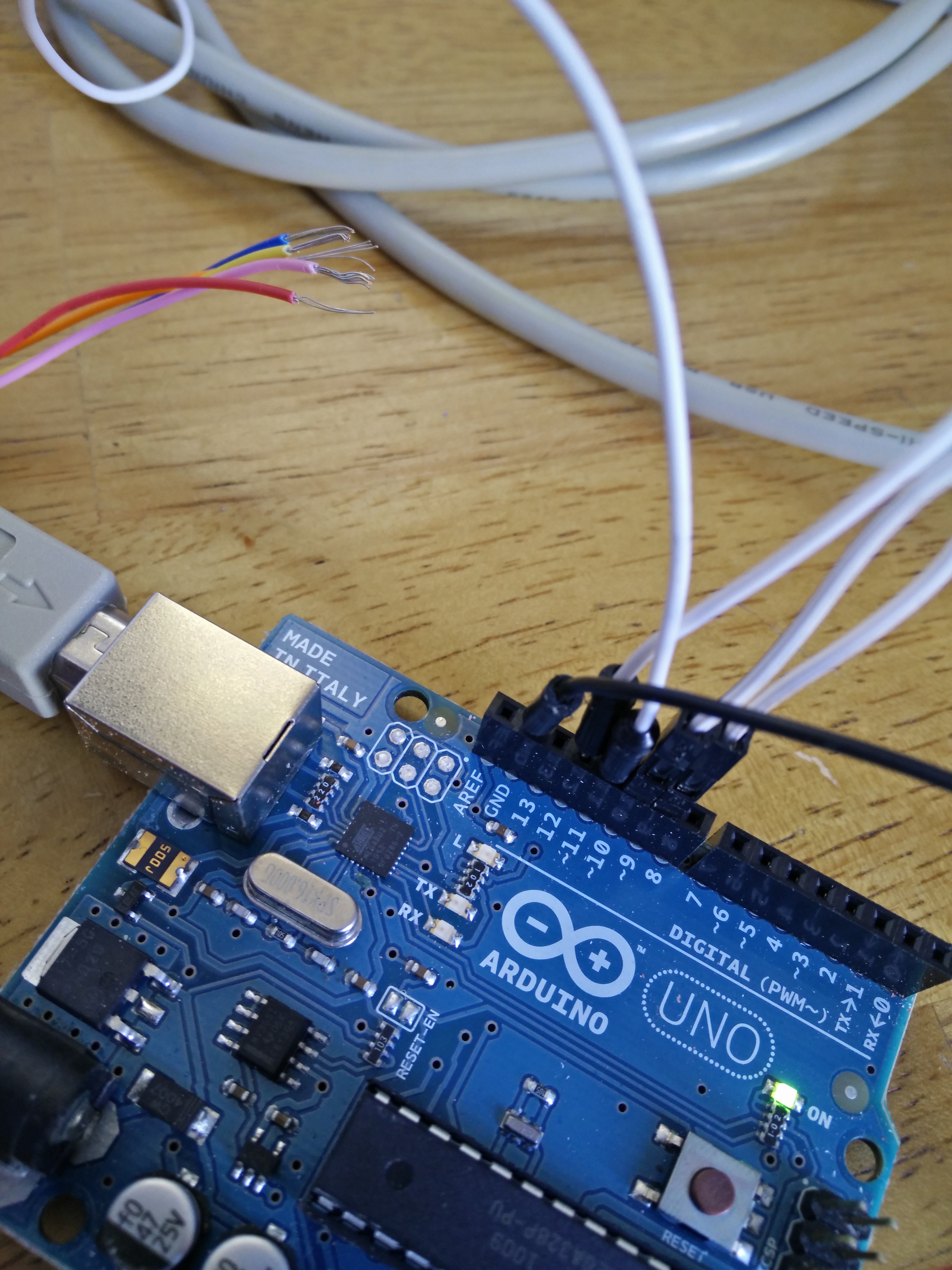
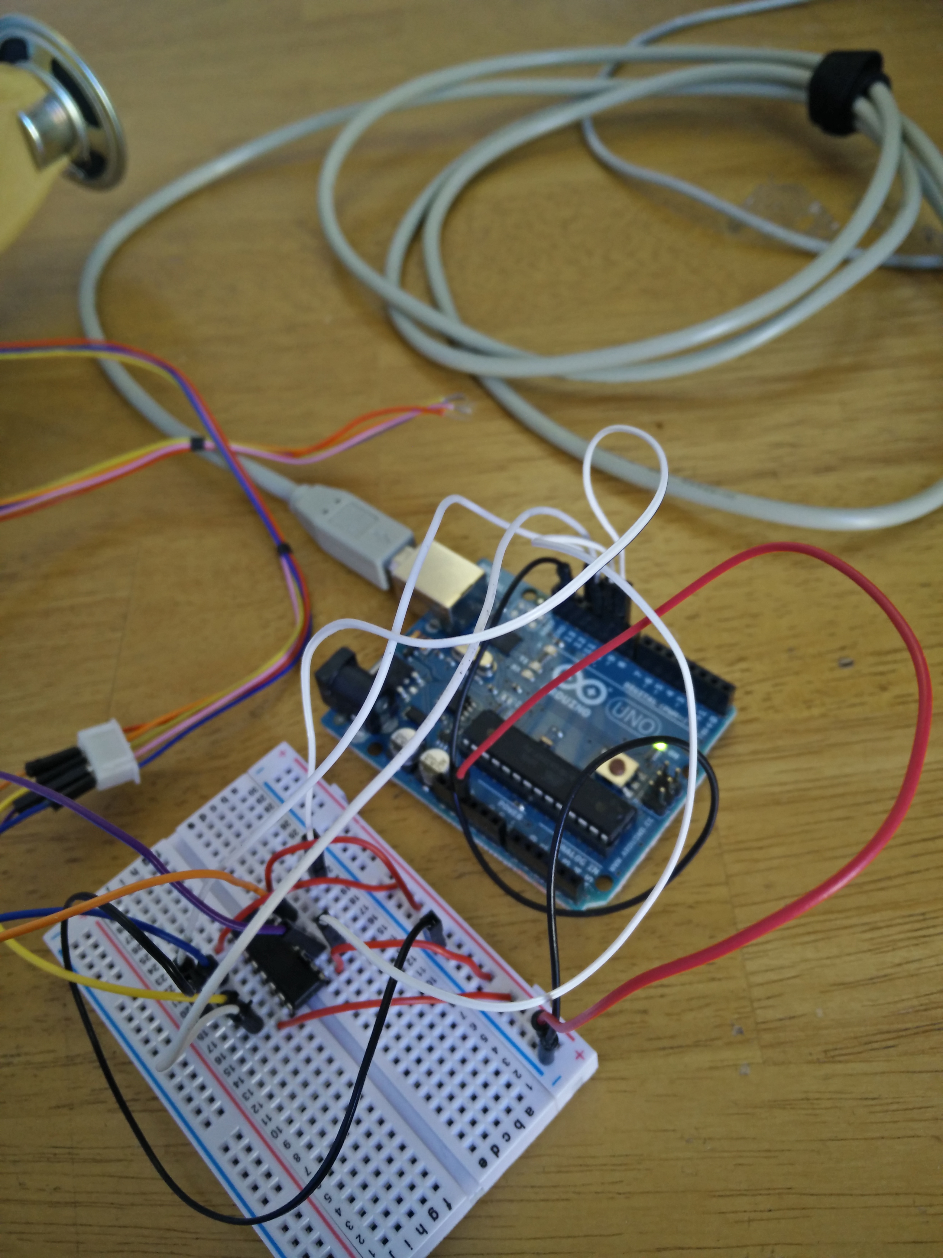
For this robot arm, I will be focusing on the Arduino because it is simple while still allowing for dynamic integration. I also like the arduino because all the external equipment you need is a computer and the cord to connect the two. While this may seem basic to some more experience Makers it is important to understand the most basic logic a computer goes through to control the arm. Understanding the basic functionality will help you scale the project later on if you want to, incorporating controls like a rotary encoder or buttons that will give the robot more finite reactionary controls.

arduino

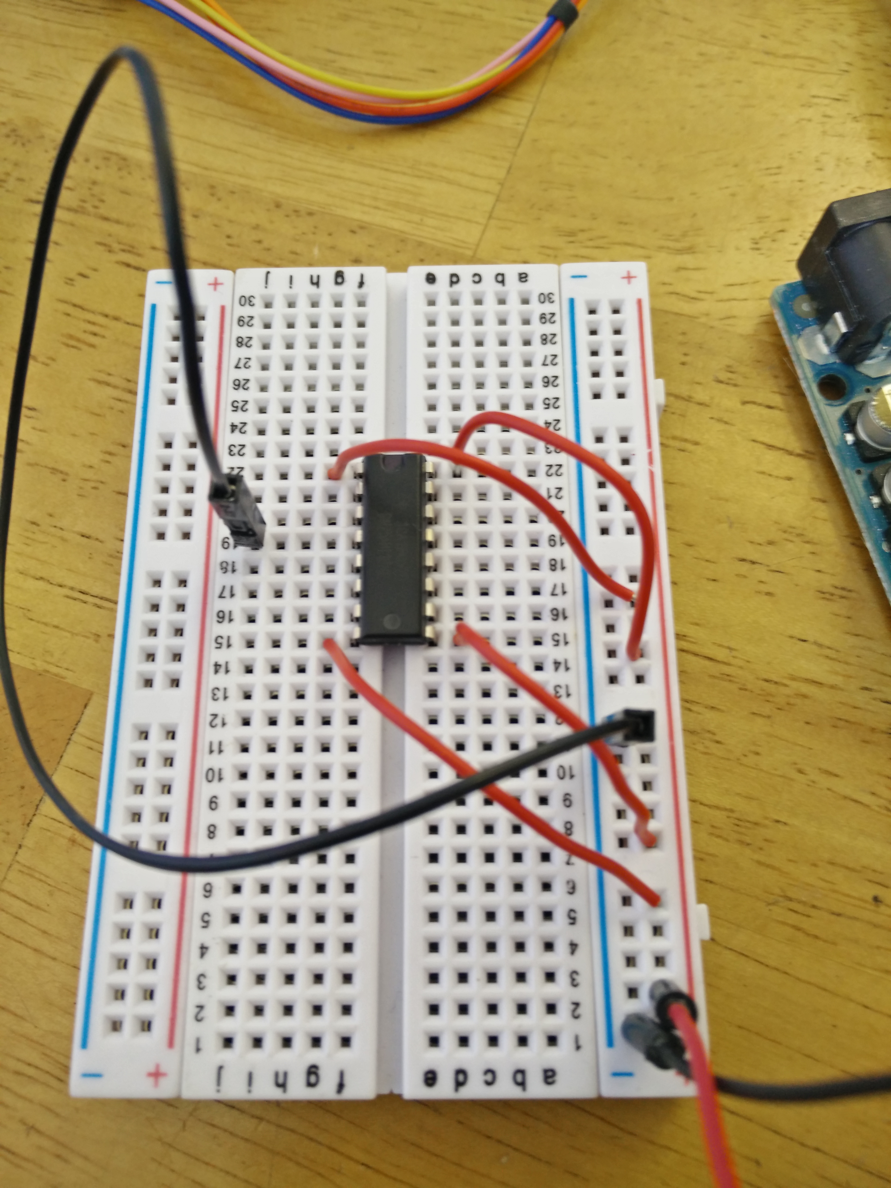
Another important part about adding complexity one step at a time is that if mistakes or miscalculations are made you are not already so far along in the project it becomes a problem to fix the errors. This is one of the main reasons why we use a breadboard in our projects before we solder them together and put them in place. A good example of this is the fact that I underestimated the strength of my base motor. This means that it is not powerful enough to move the whole arm at once, only the top section will articulate. If I had begun to add unneeded complexity and solder my arm then there would have been a lot more work for me to correct. Now I have options: I can lighten the arm or I can add a more powerful motor.

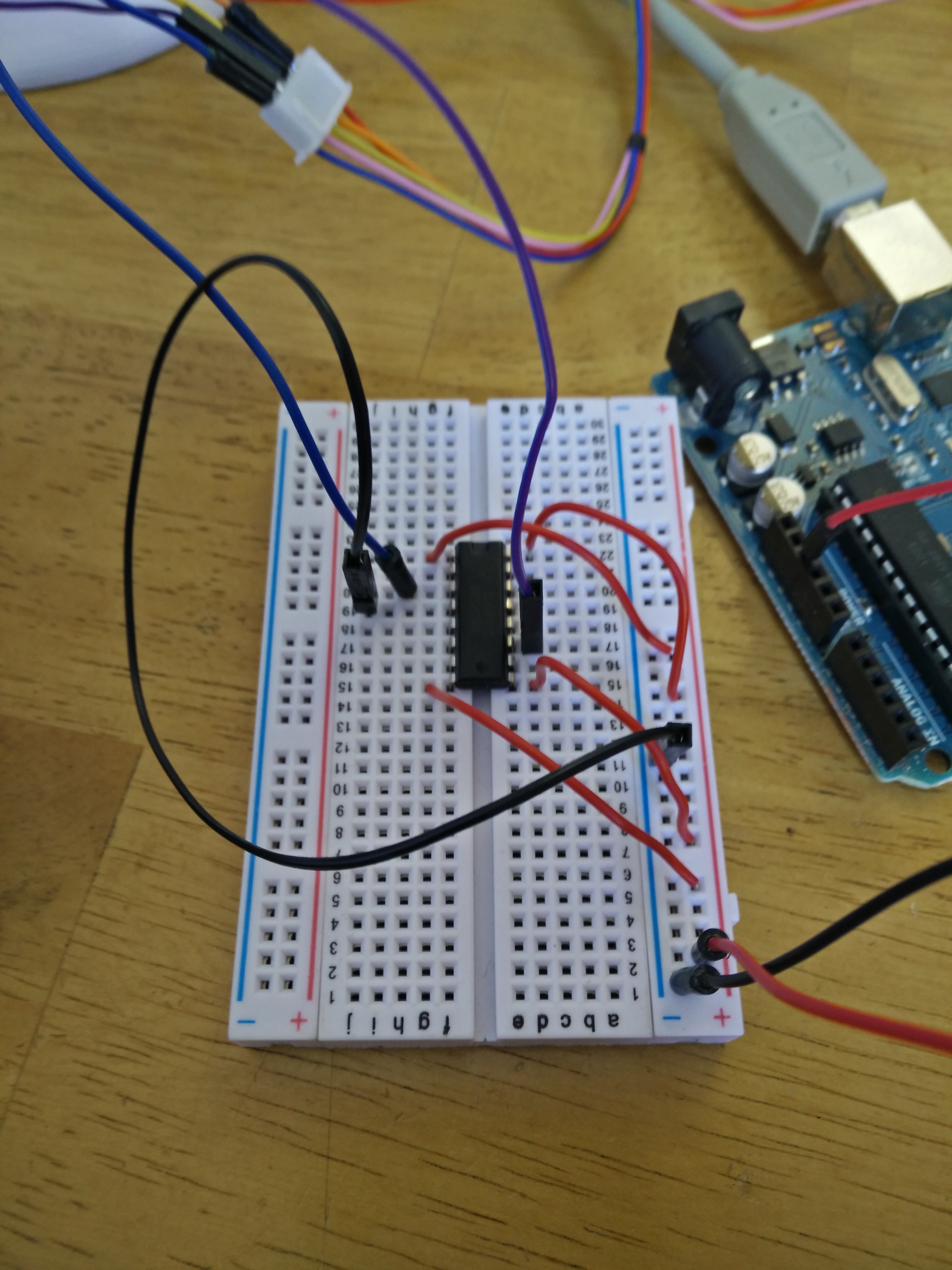
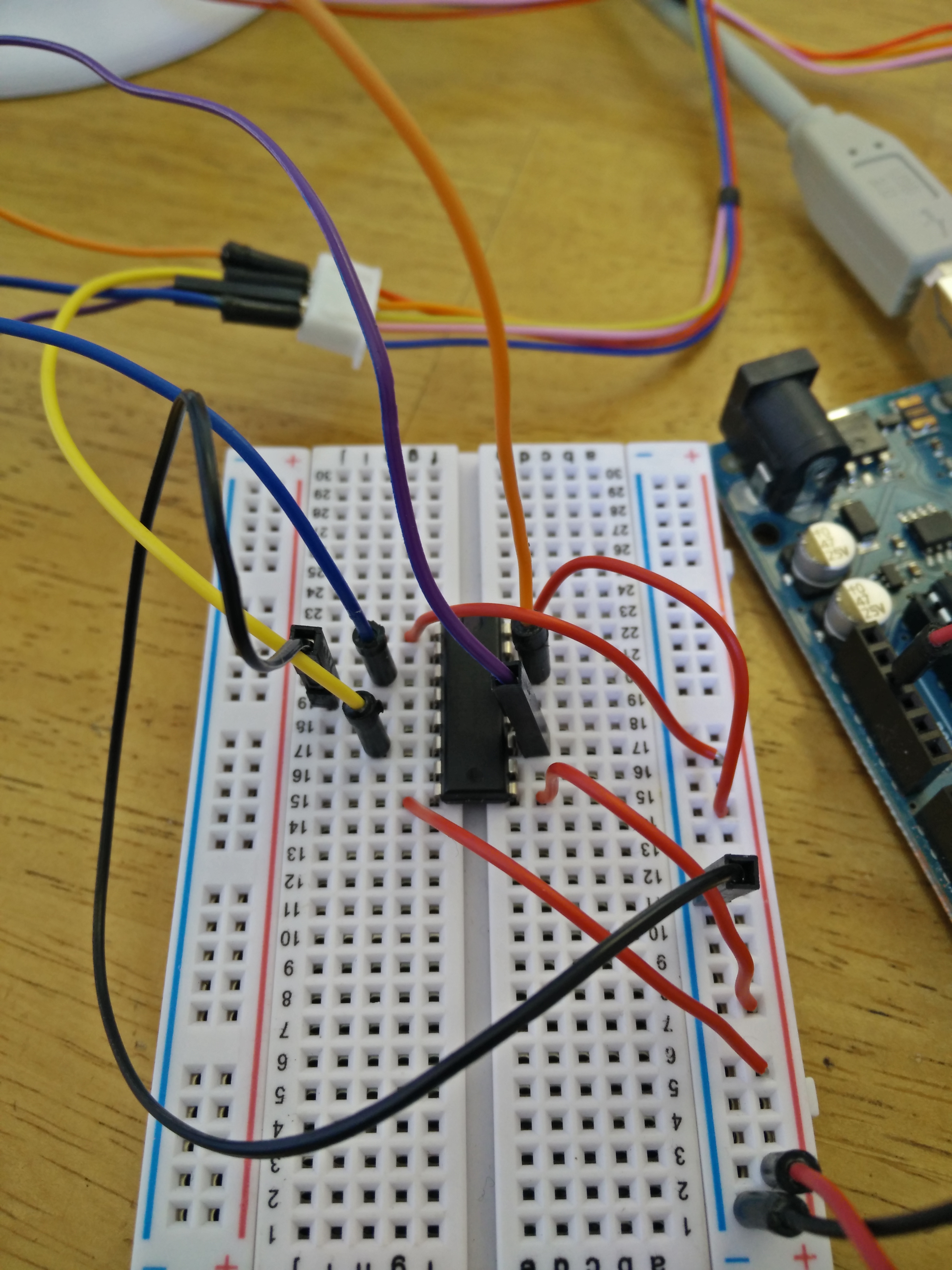
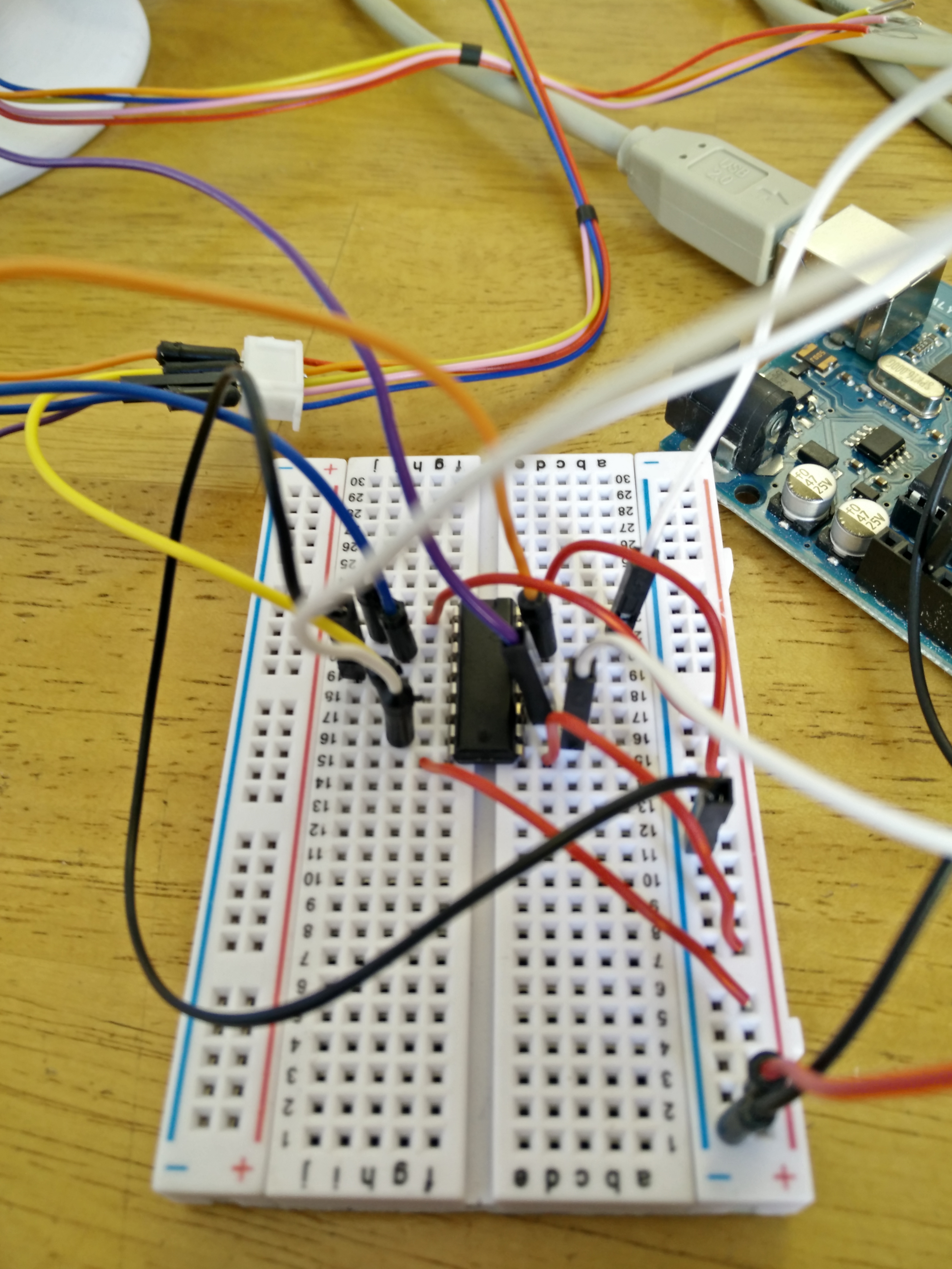
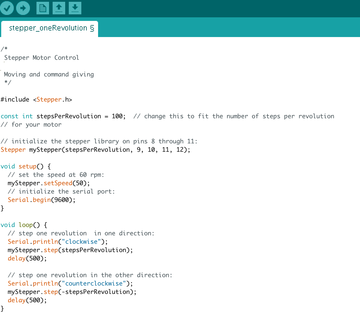
That is a problem we will address in time, for now, the upper section will articulate so I will show you how to control the motor and give it movement commands in Arduino.

Project Steps

H bridge

The first step is to get an H bridge. An H bridge is a type of Bi-polar stepper motor driver.

There are a few options when choosing an H bridge. Most people use the L293D integrated chip, but I used the SN754410 integrated circuit. While there are some very minute differences, they have the same pin layout and the same function.

Plug-in power and ground

Here we get to wiring up the breadboard and Arduino. I plugged 4 different wires into the pins on the Arduino. These wires will be used to send signals to the motor.

I also plugged the 4 voltage pins into the voltage rail and then plugged the voltage rail into the 5V pin on the Arduino. The voltage pins are 1, 8, 9, and 16.

NOTE: When reading pins on an integrated circuit read from the immediate left of the little divot at the top, down the left, across to the other side, and then back up the right. That order is very important. If you get confused please reference the circuit drawing.

Lastly, I connected a line from the ground on the Arduino to one of the 4 ground pins in the H bridge.

Plug the motor into the H bridge

Plug the motor into the H bridge. I have made sure the colors of my wires correspond to the colors of the motors wires.

Blue plugs into pin 3 of the H bridge

NOTE: The diagram’s colors don’t match, please be aware.

Yellow plugs into pin 6 of the H bridge

NOTE: The diagram’s colors don’t match, please be aware.

Pink/Purple plugs into pin 11 of the H bridge

NOTE: The diagram’s colors don’t match, please be aware.

Orange plugs into pin 14 of the H bridge

NOTE: The diagram’s colors don’t match, please be aware.

Plug the Arduino into the H bridge

Lastly, we will plug the Arduino into the H bridge. Again we do this in a specific order because we will have to declare each pin in the code.

  • Pin 12 plugs into pin 2 of the H bridge
  • Pin 11 plugs into pin 7 of the H bridge
  • Pin 10 plugs into pin 10 of the H bridge
  • Pin 9 plugs into pin 15 of the H bridge

You are now all connected; plug your Arduino into your computer and open the Arduino IDE.

Coding and Control

Copy this code:


/*
 Stepper Motor Control

 Moving and command giving
 */

#include

const int stepsPerRevolution = 100; // change this to fit the number of steps per revolution
// for your motor

// initialize the stepper library on pins 8 through 11:
Stepper myStepper(stepsPerRevolution, 9, 10, 11, 12);

void setup() {
  // set the speed at 60 rpm:
  myStepper.setSpeed(50);
  // initialize the serial port:
  Serial.begin(9600);
}

void loop() {
  // step one revolution in one direction:
  Serial.println("clockwise");
  myStepper.step(stepsPerRevolution);
  delay(500);

  // step one revolution in the other direction:
  Serial.println("counterclockwise");
  myStepper.step(-stepsPerRevolution);
  delay(500);
}

Now click auto format (this will format the code so it looks like mine).

The line I have highlighted in the second image is how to control the rotation. Using this variable you will be able to incorporate logic into the robot arm as you like. I would recommend that you play with this very basic code first before adding logic to see how many steps you will need to make one rotation.

Conclusion

After all of that modeling, printing, and work it is nice to see a finished working product. Still, this is the first step in making functional robotics. All robots start off simple and rough around the edges, the fun part and the interesting part is when Makers (like you or me) take these ideas and turn them into something really innovative and fun.

I hope this project has inspired you to make your own robots!