About this project
What is more fascinating than a brain-controlled helicopter that can be flown using nothing more than your brainwaves? When wearing your OpenBCI headset, you’ll be able to control a toy helicopter through focused concentration or by closing your eyes.
Components and Supplies
Get the hardware
We need four essential things to “hack” the helicopter tottle:
- Digital Potentiometer (DigiPot) from Microchip Technology. You can check the Digital Potentiometer documentation file here. The digiPot ranges from 0 to 5K, so plan to use the only 1/10th of the digiPot wiper range.

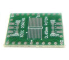
- PCBs & Breadboard 0.65mm Pitch SOIC (20 pins) to DIP Adapter from SchmartBoard. You can download the documentation file here. We will use this adapter to connect the helicopter remote controller to the new potentiometer and the Arduino board.
- A helicopter toy from Amazon. It’s a kid toy, but it works perfectly for what we want to do. You can even choose the color that you prefer among blue, red, and yellow. The helicopter comes with a remote controller, USB charger, and manual instructions. You can buy it here.


- Arduino UNO. Arduino Uno board makes it very easy to use the ATmega328 (datasheet) processor by providing easy access to most of the pins via the headers. Also, it has 14 digital input/output pins (of which six can be used as PWM outputs), six analog inputs, a 16 MHz quartz crystal, a USB connection, a power jack, an ICSP header and a reset button. It contains everything needed to support the microcontroller; simply connect it to a computer with a USB cable or power it with an AC to DC adapter or battery to get started. You can find more info and buy it here.

Get the software
- Arduino Software (IDE). The open-source Arduino Integrated Development Environment – or Arduino Software (IDE) – contains a text editor for writing code, a message area, a text console, a toolbar with buttons for common functions and a series of menus. It connects to the Arduino hardware to upload programs and communicate with them.
- OpenBCI GUI_Helicopter_Throttle based in Processing (Java). The OpenBCI GUI The Helicopter code for now only runs on Processing version 2.2.1. Please, download the version here.
Set up the hardware
First of all, we are going to remove the potentiometer from the remote controller and attached two jumpers where it was placed, so as we can create a “new potentiometer” regulated by the alpha waves registered with the OpenBCI board. How? We are going to use a digital potentiometer that will be connected to the Arduino UNO.
STEP 1: Open the cover of the remote controller.
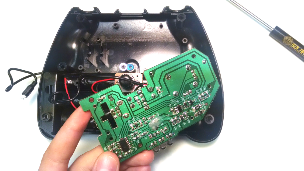
Once we have all the components listed above, we need to remove the potentiometer included in the transmitter of the helicopter.

STEP 2: Identify and remove the potentiometer.
Next step is to remove the board from the remote control, identify, and de-solder the throttle control potentiometer.
STEP 3: Attach two jumpers where the potentiometer was placed.
We attach two jumpers where the throttle helicopter potentiometer was set. The green jumper is placed in the top-left pin and the black in the bottom-left pin. We pass the jumpers into the remote control hole (such as it appears in Figure 3) just to make the connection easier.

STEP 4 (optional): Put the cover back
If you want to put the cover back, it’s completely up to you. We won’t touch anything else from he remote controller, so I would make sense to put the cover back.
STEP 5: Connect the DigiPot to Arduino UNO.
This step is important, and you better pay attention to the connections. You must follow the schematics shown in the figure below to connect the digital potentiometer to the Arduino board correctly.

STEP 6: Attach the jumpers from the remote controller to DigitPot.
We connect the jumpers that we soldered earlier in the remote controller to the DigiPot situated on the breadboard. Accordingly to the documentation, the top jumper (green jumper in Figure 4) must be connected to pin 13, while the lower jumper (black jumper in Figure 3) must be connected to pin 12.

STEP 7: Revise the connections.
The hardware part is set up! Now you are ready to get the software ready and start flying the toy helicopter with your brain waves!

Set Up the Software
STEP 1: Download Arduino code and OpenBCI GUI
The throttle control code is in the Processing sketch tabs ‘EEG_Processing‘ and ‘Helicopter‘. The GUI already has a peak detection, so we look to see if the peak is in the alpha range. If it is, and if it’s strong enough against the background noise, then a character is sent out to the Arduino that controls the helicopter. The strength of the alpha wave is encoded in the characters ‘A’ to ‘Z’. Then Processing sends the prefix ‘$’ followed by the character code. Arduino gets the prefix, and then apply the next value it gets to the potentiometer. It all took about half a day of hacking on the original OpenBCI_GUI, so I’m sure there’s room for improvement. You can download both the Arduino code and the OpenBCI GUI here.
Take the entire OpenBCI_GUI folder and put it in your Documents/Processing folder. If you already have an OpenBCI_GUI and don’t want to over-write it, create a subfolder in the Processing folder called ‘copter control’ for this one to live in.
Take the entire ‘CopterControl‘ folder and put it in your Arduino folder: Documents/Arduino
STEP 3: Upload Arduino code to Arduino UNO
For this setup, you need to plot the Arduino board with a USB to the computer. You must choose in Tools > Board the Arduino board that you are using. In our case, we are using “Arduino/Genuino UNO” connected to a digital potentiometer connected to the hacked throttle control of a toy helicopter. Also, do not forget to select the serial port of the Arduino. If you have Windows, you will see your port name under the name of “COM X“, whereas you will see “/dev/tty.usbmodem14131” if you own either a Mac or a Linux OS X.

Helicopter Control
The Helicopter Control code controls the toy helicopter by receiving the information sent by the Processing code via characters and creating a channel of communication with the digital potentiometer.
First of all, we need to include the libraries that we want to use, and create the variables that we will use to determine when the helicopter has to fly or not. Also, we need the define the variables from the digipot accordingly to the pins that we used to set up the hardware.
// include SPI library
#include <SPI.h>
// digitPot defines
#define CS 10
#define RST 9
#define READ_REG 0x0C
#define WRITE_REG 0x00
#define INCR 0x04
#define DECR 0x08
#define TCON0 0x40
#define TCON1 0xA0

// create variables
boolean testingPot = false; // used to test initial pot function
boolean expectingValue = false;
boolean throttling = false;
unsigned long throttleTimer;
int throttleDuration = 2000; // 2 seconds of throttle duration
byte throttleSetting = 0x00;
byte lastThrottleSetting;
byte wiper[4] = {0x00, 0x10, 0x60, 0x70}; // address of each wiper register
byte wiperPos[4] = {0x01, 0x02, 0x03, 0x04};
int resistance;
After that, we setup the serial port with the baud rate from the Arduino board. Also, we configure the pins mode and the digital writes accordingly to Figure 4; we preset a delay, and we start with the throttle down.
void setup() {
Serial.begin(115200);
SPI.begin();
SPI.beginTransaction(SPISettings(10000000, MSBFIRST, SPI_MODE0));
Serial.println("OpenBCI Alpha Wave Helicopter Control");
pinMode(CS,OUTPUT); digitalWrite(CS,HIGH);
pinMode(RST,OUTPUT); digitalWrite(RST,LOW); // digipot reset pin active low
delay(100); digitalWrite(RST,HIGH);
throttleDown();
throttleSetting = lastThrottleSetting = 0x00;
Serial.print("trottle: ");Serial.println(throttleSetting);
}
We create a loop based on time to control the time the helicopter is up and down, and we set a resistance for the throttle.
void loop() {
 if((millis() - throttleTimer > throttleDuration) && throttling){
  throttleSetting = 0;
  throttleDown();
  throttling = false;
 }
 if(throttleSetting != lastThrottleSetting){
  setResistance(throttleSetting);
  Serial.print("trottle: ");Serial.println(throttleSetting,DEC);
  lastThrottleSetting = throttleSetting;
 }
 eventSerial();
}
We configure the event serial to receive the characters sent from the OpenBCI GUI. The expecting value is ASCII encoded and goes from A to Z (26 letters), where A=0, B=1, C=2, and so on. These values are proportionally related the “strength” controlsof the alpha waves registered in the OpenBCI GUI.
void eventSerial(){
 while (Serial.available()) {
  char inChar = (char)Serial.read();
  // Serial.print("Received "); Serial.println(inChar);
   if(expectingValue){
    throttleSetting = byte(inChar - 'A');
    // variable is ascii encoded 0=A, 1=B, etc
    throttleSetting = map(throttleSetting, 0,26,0,255);
    // Serial.print("trottle: ");Serial.println(throttleSetting);
    throttleTimer = millis();
    throttling = true;
    expectingValue = false;
    return; // get outa here
  }
 Serial.print("Received "); Serial.println(inChar);
 switch (inChar) {
  // Processing must send the $ to tell Arduino the next value is special
  case '$':
   if(expectingValue){
    return;
   }
   throttleUp();
   expectingValue = true;
   break;
   default:
   break;
   }
 }
}
The Digital Potentiometer
The DigiPot code controls the digital potentiometer connected to the Arduino. There are five void functioncontrol when the helicopter goes up and down, how to set the resistance, when to read wipers, and when to check possible errors.
The throttleDown() sets the digpot wipers to full on for lowest current output. Digital writes are activated or disconnected depending on the inputs.
void throttleDown(){ // set the digipot wipers to full on for lowest current output
 byte command, error;
 digitalWrite(CS,LOW); // activate with W & B connected, A disconnected
 error = SPI.transfer(TCON0 | WRITE_REG);
 SPI.transfer(0xBF); // 1011 1111 // connect A for testing resistance
 checkError(error,TCON0);
 digitalWrite(CS,HIGH);
 delay(1);
 digitalWrite(CS,LOW);
 error = SPI.transfer(TCON1 | WRITE_REG);
 SPI.transfer(0xBB); // 1011 1011
 digitalWrite(CS,HIGH);
 checkError(error,TCON1);
 for(int i=0; i<4; i++){
  digitalWrite(CS,LOW);
  error = SPI.transfer(wiper[i] | WRITE_REG);
  SPI.transfer(0x00); // connect W to B only see W resistance
  digitalWrite(CS,HIGH);
  checkError(error,wiper[i]);
 }
 Serial.println("throttled down");
}
The throttleUp() works the same way as the trottleDown() and it is activated depending on the CS input that comes from the Arduino.
void throttleUp(){
 byte error;
 digitalWrite(CS,LOW); // activate with only Pot 0 engaged [lower right]
 error = SPI.transfer(TCON0 | WRITE_REG);
 SPI.transfer(0x8F); // 1000 1111 // connect A for testing resistance
 checkError(error,TCON0);
 digitalWrite(CS,HIGH);
 delay(10);
 digitalWrite(CS,LOW);
 error = SPI.transfer(TCON1 | WRITE_REG);
 SPI.transfer(0x88); // 1000 1000
 digitalWrite(CS,HIGH);
 checkError(error,TCON1);
}
The following functions are related wit the resistance set up, the wipers reading, and checking possible errors through the Arduino code.
void setResistance(byte r){
 byte error;
 digitalWrite(CS,LOW); // activate with W & B connected, A disconnected
 error = SPI.transfer(wiper[0] | WRITE_REG);
 SPI.transfer(r);
 digitalWrite(CS,HIGH);
 checkError(error,wiper[0]);
}

void readWipers(){
 byte error;
 for(int i=0; i<4; i++){
  digitalWrite(CS,LOW);
  error = SPI.transfer(wiper[i] | READ_REG);
  wiperPos[i] = SPI.transfer(0x00); // read wiper values
  digitalWrite(CS,HIGH);
  checkError(error,wiper[i]);
 }
}

void checkError(byte e, byte r){
 if(e != 0xFF){
  Serial.print("\terror: on register "); Serial.println(r,HEX);
 }
}
STEP 4: Update the OpenBCI GUI
The OpenBCI_GUI_Helicopter_Throttle is a variant of OpenBCI GUI that uses the strength of alpha wave to control the helicopter throttle. So, if you have the original version of OpenBCI GUI you only have to add the helicopter class, replace the EEG Processing file with the new one, and add some lines of code to the OpenBCI GUI file.

This program looks for peaks in the alpha band, and it displays a real-time peak detector in the FFT plot (see Figure 9). When there is a dominant alpha wave present, the peak marker, a small circle, will darken (become bold). There is a short dashed line that references the background level the peak is measured against. Each channel has a peak detector and a background marker in its color. The most visceral way to understand how it works is to watch it. Use the Synthetic setting in the GUI, or to playback from an existing file of real EEG data.
“OpenBCI_GUI.pde” Tab
Remember to change the port name in the code above depending on the OS that you have on your computer. If you have Windows, you must write your port name as it follows “COM X“, whereas type “/dev/tty.usbmodem14131” if you own either a Mac or an OS X.
//define Helicopter
String helicopter_portName = "COM87"; //starts as N/A but is selected from control panel to match your OpenBCI USB Dongle's serial/COM
Serial helicopter_serial;
int helicopter_baud = 115200; //baud rate from the Arduino
Helicopter helicopter;
 //apply additional processing for the time-domain montage plot (ie, filtering)
 eegProcessing.process(yLittleBuff_uV,dataBuffY_uV,dataBuffY_filtY_uV,fftBuff);
 //apply user processing
 // ...yLittleBuff_uV[Ichan] is the most recent raw data since the last call to this processing routine
 // ...dataBuffY_filtY_uV[Ichan] is the full set of filtered data as shown in the time-domain plot in the GUI
 // ...fftBuff[Ichan] is the FFT data structure holding the frequency spectrum as shown in the freq-domain plot in the GUI
 eegProcessing_user.process(yLittleBuff_uV,dataBuffY_uV,dataBuffY_filtY_uV,fftBuff);
“EEG_Processing.pde” Tab
The first step is to find the frequency with the highest value in a given channel’s FFT by sorting through the channel’s FFT bin values. The variable min_allowed_peak_freq_Hz [4.5] and max_allowed_peak_freq_Hz [15.0] create a window of frequencies to consider a peak candidate. In other words, the peak that is detected must be at least 4.5Hz and no more than 15Hz. That is a way to try and avoid noise. Frequencies outside the alpha band are not considered.
class EEG_Processing_User {
 private float fs_Hz; //sample rate
 private int nchan;

 // THE CRITICAL DETECTION PARAMETER!!!!
 final float detection_thresh_dB = 6.0f;
 //how much bigger must the peak be relative to the background

 //add your own variables here
 final float min_allowed_peak_freq_Hz = 4.5f; //was 4.0f, input, for peak frequency detection
 final float max_allowed_peak_freq_Hz = 15.0f; //was 15.0f, input, for peak frequency detection
 final float[] processing_band_low_Hz = {
 4.0, 6.5, 9, 13.5
 }; //lower bound for each frequency band of interest (2D classifier only)
 final float[] processing_band_high_Hz = {
 6.5, 9, 12, 16.5
 }; //upper bound for each frequency band of interest
 DetectedPeak[] detectedPeak; //output per channel, from peak frequency detection
 DetectedPeak[] peakPerBand;
 Helicopter helicopter;
 boolean showDetectionOnGUI = true;
 public boolean useClassfier_2DTraining = false; //use the fancier classifier?

 //class constructor for user defined signal processing rules
 EEG_Processing_User() {
 } //empty
 EEG_Processing_User(int NCHAN, float sample_rate_Hz, Helicopter copter) {
 nchan = NCHAN;
 fs_Hz = sample_rate_Hz;
 helicopter = copter;
 detectedPeak = new DetectedPeak[nchan];
 for (int Ichan=0; Ichan<nchan; Ichan++) detectedPeak[Ichan]=new DetectedPeak();

 int nBands = processing_band_low_Hz.length;
 peakPerBand = new DetectedPeak[nBands];
 for (int Iband=0; Iband<nBands; Iband++) peakPerBand[Iband] = new DetectedPeak();
 }

//

 //here is the processing routine called by the OpenBCI main program...update this with whatever you'd like to do
 public void process(float[][] data_newest_uV, //holds raw EEG data that is new since the last call
 float[][] data_long_uV, //holds a longer piece of buffered EEG data, of same length as will be plotted on the screen
 float[][] data_forDisplay_uV, //this data has been filtered and is ready for plotting on the screen
 FFT[] fftData) {

 if (false) {
 // to target one channel, go here
 processSingleChannel(data_newest_uV, data_long_uV, data_forDisplay_uV, fftData);
 } else {
 // to target multiple channels, go here
 processMultiChannel(data_newest_uV, data_long_uV, data_forDisplay_uV, fftData);
 }
 } // end of process
The next step is to average the other FFT bin values around the peak bin to see if the peak ‘stands out’ against the background. The function called findPeakFreqeuncy in EEG_Processing.pde does all this work to find the largest peak in the signal. It also sets variables, like the level in dB of the peak and the level of dB of the background. It will measure the difference between the peak and the background, and test the difference against a threshold. The variable detection_thresh_dB [set to 6.0] is the threshold in dB above the background that the detectedPeak frequency needs to be to trigger an event. In this case, when the peak is 6.0dB bigger or more than the background, it will be considered a ‘detected peak’.
 void findPeakFrequency(FFT[] fftData, int Ichan) {

 float FFT_freq_Hz, FFT_value_uV;

 //clear the data structure that will hold the peak for this channel
 detectedPeak[Ichan].clear();

 //loop over each frequency bin in this channel to find the one with the strongest peak
 int nBins = fftData[Ichan].specSize();
 for (int Ibin=0; Ibin < nBins; Ibin++) {
 FFT_freq_Hz = fftData[Ichan].indexToFreq(Ibin); //here is the frequency of this bin of this channel

 //is this bin within the frequency band of interest?
 if ((FFT_freq_Hz >= min_allowed_peak_freq_Hz) && (FFT_freq_Hz <= max_allowed_peak_freq_Hz)) {
 //we are within the frequency band of interest

 //get the RMS voltage per bin (must div by nBins)
 FFT_value_uV = fftData[Ichan].getBand(Ibin) / ((float)nBins);
 //FFT_value_uV = fftData[Ichan].getBand(Ibin);

 //decide if this is bigger, compared to previous bins for this channel
 if (FFT_value_uV > detectedPeak[Ichan].rms_uV_perBin) {
 //this is bigger, so hold onto this value as the new "maximum"
 detectedPeak[Ichan].bin = Ibin;
 detectedPeak[Ichan].freq_Hz = FFT_freq_Hz;
 detectedPeak[Ichan].rms_uV_perBin = FFT_value_uV;
 }
 } //close if within frequency band
 } //close loop over bins to find peak

 // loop over the bins again (within the sense band) to get the average background power,
 // excluding the bins on either side of the peak
 float sum_pow=0.0;
 int count=0;
 for (int Ibin=0; Ibin < nBins; Ibin++) {
 FFT_freq_Hz = fftData[Ichan].indexToFreq(Ibin);
 if ((FFT_freq_Hz >= min_allowed_peak_freq_Hz) && (FFT_freq_Hz <= max_allowed_peak_freq_Hz)) {
 if ((Ibin < detectedPeak[Ichan].bin - 1) || (Ibin > detectedPeak[Ichan].bin + 1)) {
 FFT_value_uV = fftData[Ichan].getBand(Ibin) / ((float)nBins); //get the RMS per bin
 sum_pow+=pow(FFT_value_uV, 2.0f);
 count++;
 }
 }
 }
 //compute mean
 detectedPeak[Ichan].background_rms_uV_perBin = sqrt(sum_pow / count);

 //decide if peak is big enough to be detected
 detectedPeak[Ichan].SNR_dB
 = 20.0f*(float)java.lang.Math.log10(detectedPeak[Ichan].rms_uV_perBin
 / detectedPeak[Ichan].background_rms_uV_perBin);

 //if ((detectedPeak[Ichan].freq_Hz >= processing_band_low_Hz[0])
 // && (detectedPeak[Ichan].freq_Hz <= processing_band_high_Hz[0])) {
 // if (detectedPeak[Ichan].SNR_dB >= detection_thresh_dB-2.0) {
 // detectedPeak[Ichan].threshold_dB = detection_thresh_dB;
 // detectedPeak[Ichan].isDetected = true;
 // }
 //} else {
 // if (detectedPeak[Ichan].SNR_dB >= detection_thresh_dB) {
 // detectedPeak[Ichan].threshold_dB = detection_thresh_dB;
 // detectedPeak[Ichan].isDetected = true;
 // }
 //}

 //} // end loop over channels
 } //end method findPeakFrequency
The other thing I will add is that the method of measurement is specific. We measure the SNR, Signal to Noise Ratio. This is a measurement that is in RMS Voltage per bin. In this case, the FFT value of each bin (frequency) is delivered in RMS, but then it needs to be divided by the number of bins to get the RMS per bin [RMS/bin] this is a weird number, and very scientific. There is squaring and square-rooting going on all over the place, and the calculations can be found in the findPeakFrequency function in the EEG_Processing.pde tab if you want to dig into it.

The function processMultiChannel() maps the values to the Helicopter. If there is a peak detection in the alpha range, and if it’s strong enough against the background noise, then a character is sent out to the Arduino that controls the helicopter. The strength of the alpha wave is encoded in the characters ‘A’ to ‘Z’.
public void processMultiChannel(float[][] data_newest_uV, //holds raw EEG data that is new since the last call
 // create variables
 float[][] data_long_uV, //holds a longer piece of buffered EEG data, of same length as will be plotted on the screen
 float[][] data_forDisplay_uV, //this data has been filtered and is ready for plotting on the screen
 FFT[] fftData) { //holds the FFT (frequency spectrum) of the latest data
 boolean isDetected = false;
 int lastPeak = 0;
 int peakChan = 0;
 String mappedValue = "";

 // passes a mappedValue to the Helicopter. mapping is done here
 for(int i=0; i<nchan; i++){
  findPeakFrequency(fftData, i); // look for the peak freq on this channel
  // first check that any detectedPeaks are in the desired freqeuency range
  if ((detectedPeak[i].freq_Hz >= processing_band_low_Hz[3-1]) && // <= 9Hz line 48
   (detectedPeak[i].freq_Hz < processing_band_high_Hz[3-1])) { // < 12Hz line 50
   // then measure the peak against the background
   if (detectedPeak[i].SNR_dB >= detection_thresh_dB) {// if it is pronounced
    detectedPeak[i].threshold_dB = detection_thresh_dB;
    // on the fly threshold adjust (?)
    println("detectedPeak channel " + (i+1) + " = " + detectedPeak[i].SNR_dB);
    // verbose debug
    int peak = int(detectedPeak[i].SNR_dB) + 'A'; // map SNR.dB to ASCII Helicopter command
   if(peak > lastPeak) { lastPeak = peak; peakChan = i+1;
   }
  detectedPeak[i].isDetected = true;// flag that we got a winner
  isDetected = true; // uncomment for verbose output
   if (isDetected) {
   //print some output
   println("EEG_Processing_User: alpha!, Chan " + (i+1) + ", peak = " + detectedPeak[i].rms_uV_perBin + " uV at "
   + detectedPeak[i].freq_Hz + " Hz with background at = " + detectedPeak[i].background_rms_uV_perBin
   + ", SNR (dB) = " + detectedPeak[i].SNR_dB + " " + mappedValue);
   // isDetected = false;
   }
  }
 }
 }
 if(isDetected){
  mappedValue += char(lastPeak);
  println("Detected Peak on chan " + peakChan + " Mapped Value: " + mappedValue);
  helicopter.throttle(mappedValue); // send the ASCII command to the hacked helicopter
  }
} // end of processMultiChannel
“Helicopter.pde” Tab
The Helicopter class has an inner class called Command that controls the helicopters commands and receives the mapped values from EEG_Processing. Then, the same class sends the prefix ‘$’ followed by the character code from EEG_Processing. Arduino gets the prefix, and then apply the next value it gets to the potentiometer.
class Helicopter {
 // create an inner class command
 class Command {
 private String command_str;
 private String variable_str;
 private String name;
 private int counter;
 private Serial serial_h;
 public boolean printReceivedCommand = true;
 // public int ID;

 Command(Serial _serial_h, String _str, String _name, int _ID) { // String _var,
 serial_h = _serial_h;
 command_str = _str;
 name =_name;
 counter = 0;
 }

 public void issue() {
 counter++;
  if (printReceivedCommand) {
   println("Helicopter: Command: " + name + " (" + counter + ")");
  }
  // println("A"); // verbose debug
  if (serial_h != null) serial_h.write(command_str);
  // println("B"); // verbose debug
  }
 } //close definition of class Command

 private Command command_throttle;//, // Helicopter command

 private String mappedValue; // variable to control helicopter throttle
 private int counter = 0;

 //Constructor, pass in an already-opened serial port
 Helicopter(Serial serialPort) {
 // empty
 }

 public void throttle(String V, int chan) {
 counter++;
  println("Helicopter 1 - Command: Throttle $" + V + " (" + counter + ")");
  helicopter_serial.write("$" + V); // shift the incoming value to ASCII
   while (helicopter_serial.available () > 0) { // hang and wait
    print(char(helicopter_serial.read())); // for the handshake
   }
 }
}
Let’s hack it!
We’ve got the helicopter and the potentiometer, we’ve uploaded the new Arduino code to the OpenBCI 32bit board, and we have the OpenBCI headset in our heads. So, we are more than ready to hack the brains and control the toy helicopter!

It is known that if you close your eyes, your Alfa waves increase instantly. That’s what I’m trying to the in the figure above. Besides, I discovered that you could also get alpha waves if you only stare at one particular point.

If you don’t believe me, the guys from Futurism did a stream live video at OpenBCI HQ, and we had the opportunity to show the World what makes OpenBCI different and what we do. Besides, you can find below an advance of what will find in the entire video. Enjoy it!

Future Improvements
Written by Joel Murphy (OpenBCI Co-founder & President) and Irene Vigue Guix (Biomedical Engineer and Neuroscientist resident at OpenBCI).

One Comment Add yours