Alasdair Allan is a scientist, author, hacker and tinkerer, who is spending a lot of his time thinking about the Internet of Things. In the past he has mesh networked the Moscone Center, caused a U.S. Senate hearing, and contributed to the detection of what was—at the time—the most distant object yet discovered.
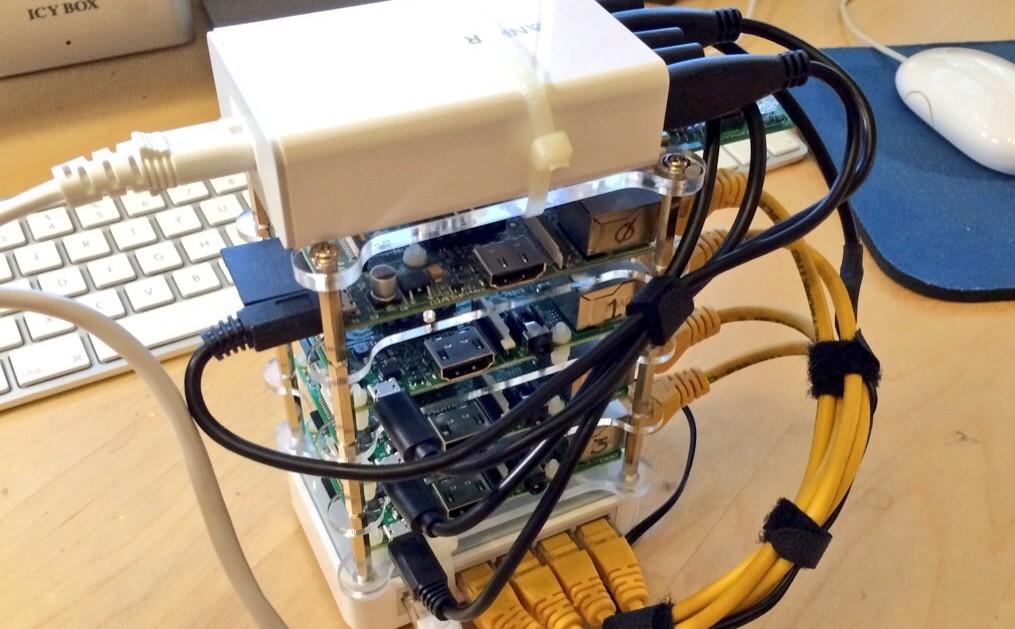
A 4-node Raspberry Pi Cluster. The top board is an original Model B, while the three below are brand new Raspberry Pi 2 boards.
Updated: This project was originally published on 26th Aug 2015 and was then updated on the 5th Sept 2015 with additional instructions on how to add a second Ethernet adaptor to the head node, and have it serve as a DHCP server for the other nodes in the cluster.
Over the weekend I sat down and built a small Raspberry Pi cluster consisting of 4 nodes. I used three Raspberry Pi 2 boards for compute nodes and an original Model B for the head node. I wanted the cluster — more commonly known as a ‘bramble’ — to be as compact as possible, with just two cables coming out, one for power and the other for network. I made use of a USB hub to power the boards, and a small Ethernet switch which I could hack to be also be powered from the USB hub rather from a separate wall wart.
However, even with just 4 nodes my pocket cluster is big enough for what I want, which is as a testbed for some distributed computing work I’m doing. The small cluster sitting on my desk lets me test code out before deploying jobs to the much more extensive, and expensive, cluster I’m using for grunt work on the project.
Not sure if Raspberry Pi is right for you? Make:’s interactive Board Guide lets you dial into the field to find the best board for your needs.
Putting together a cluster this size is actually pretty easy, after all I could just have had a pile of boards and a tangle of wires in the corner of my office and be done with it. I wanted to make my cluster as compact as possible, but I didn’t really have time to head down to my local FabLab and design an enclosure. Instead I just wanted to order all the appropriate bits and pieces and then bolt them together. Not amazingly Maker-y I know, but the cluster was a means to an end, not the project itself.
Since I had enough Raspberry Pi boards kicking around my office already, the first thing I needed was an enclosure to hold them.
The 4 board ‘dogbone’ enclosure
The enclosure I finally settled on was a four board stackable ‘dog bone’ case that I picked up on Amazon, although if you’re willing to wait a little bit there are plenty of similar cases on AliExpress that can be had for much less. It shipped overnight and I had it the next day; it was the only thing I bought to build the cluster as I had everything else on the shelf.
The 5-port USB Hub
The USB hub I used was the thing that actually inspired me to do the build in the first place: It’s a 5-port hub from Anker and has coincidentally about the same footprint as the Raspberry Pi itself. With five ports, there’s one port for each of my four Raspberry Pi boards, and a final port left over to power an Ethernet switch for the cluster.
The 5-port Ethernet Switch
My choice of Ethernet switch was entirely driven by two factors, size and voltage. I wanted it to more-or-less have the same footprint as Raspberry Pi, but I also desperately wanted it to be powered from my USB hub. So it had to take a 5V supply.
I couldn’t find a switch that was powered directly from USB, however I did find a couple on my shelves that were about the right size, and crucially could be driven using a 5V supply. That did however mean hacking a Frankenstein cable together.
The 5V power supply and a spare USB cable
The first step is to carefully snip off the end of the 5V supply cable, making sure to label which of the two wires corresponded to the two wires left attached to the power brick. Stripping off the ends of the wires you can plug the brick into the wall and use a volt meter to measure which of the two wires is +5V and which is GND.
The 5V supply cable (top) and the USB cable end (bottom)
Then snip off the end of the USB cable and carefully, as the wires inside the cable are small and delicate, strip back the cover to reveal the wires. You’re looking for the red and black wires, the others carry data. You can just cut them off, you won’t need them.
The internal wiring of a USB cable
Soldering the two end of the cables together — joining the +5V to +5V, and the GND to GND — and then covering each individual wire, as well as the join itself, with some shrink wrap gives me the Frankenstein cable I need to power the Ethernet switch from the last available port of my USB hub.
The Frankenstein cable
After searching through my stack of spare cables to find the shortest USB and Ethernet cables possible, sticking the cluster together at this point came down to cable ties and velcro.
The finished Raspberry Pi cluster
After tying everything together I added a Blinkstick for status notification, alongside a small 64GB USB flash drive for shared storage across the cluster, filling the two USB ports of the head node.
The first thing we need to do is grab a disk image of the latest version of Raspbian and copy it to four SD cards, one for each of our Raspberry Pi boards.
For now I’m taking a short cut an using my home router to allocate IP addresses to each of the nodes. Booting each Pi in turn, and taking a note of the IP address they get allocated using the router’s web interface, I ended up with the head node having an IP address of 192.168.1.173, with the three compute nodes having 192.168.1.177, 192.168.1.178, and 192.168.1.180.
Logging into the nodes in turn I did the standard setup on each node by running,
% sudo raspi-config
and the going ahead and expanding the file system to the size of the SD card, giving me a few extra gigabytes to play with. I also changed the password for each node to something a bit more secure and renamed the nodes rpi0, rpi1, rpi2, and rpi3 respectively.
After doing that I edited the /etc/hosts file on each of the nodes,
and went ahead and generated SSH keys for all four of the nodes without any pass phrases, distributing the public keys of each node to the other three. This means I can ssh between the nodes without having to repetitively type my password all the time, but will still have to type a password to ssh into the cluster.
but if you want it to automatically mount on boot you’ll need to add the following to the /etc/fstab file,
/dev/sda1 /mnt/usb auto defaults,user 0 1
However I wanted to go a bit further and make this disk available to all four of the nodes. To do this I used NFS and autofs. On all four of the nodes you’ll need to go ahead and install the NFS client software,
% sudo apt-get install nfs-common
and on rpi1, rpi2, and rpi3 you’ll need to create a mount point
After rebooting you can check from one of the compute nodes to make sure that rpi0 is exporting the disk over NFS correctly. At this point you could pretty easily just edit the /etc/fstab file and add the disks. However that might prove problematic depending on the order in which the nodes boot. Instead on all three of the compute nodes you should install autofs,
% sudo apt-get install autofs
and then edit the /etc/auto.master file adding
/mnt/nfs /etc/auto.nfs
at the end. Then create the /etc/auto.nfs file, adding,
rpi0 rpi0:/mnt/usb
and restart the autofs service,
% sudo /etc/init.d/autofs restart.
if all goes well at this point if you change to the /mnt/nfs/rpi0/ directory and the disk attached to the head node should automatically mount itself. You can check,
Alongside the USB flash drive (since I had one lying around) I installed a Blinkstick. A single software-controllable RGB LED, the stick actually comes in rather handy for server status light. It’s hard to ignore a blinking light. After slotting the stick into the head node’s last remaining USB port, you can set up the software by,
I travel a lot. That means I spend a lot of time away from my home office. While I can leave the cluster up and running and just ssh into it while I’m away, I’d actually sort of like to be able to take it on the road with me to shows. So, going forward, I’d really like just to be able to pick the cluster up and dump it down on any network.
That means I’m going to have to reconfigure the networking just a little bit.
Instead of directly connecting the Ethernet switch to the external network, and having my home router allocate IP addresses for each of the nodes, as a next step I’m going to add a USB Ethernet adaptor to the head node. This will give the head node two Ethernet connections.
The first will connect to the external network, giving the head node — and hence the cluster — an ‘external’ IP address. The second will connect to the cluster’s Ethernet switch. We can then configure the head node as a DHCP server for other three ‘internal’ nodes attached to the switch, creating a second network visible only to the cluster.
In this configuration I’ll still be able to ssh into the head node, but I’ll only be able to reach the three compute nodes from the head node. There is a problem however: How will I know the external IP address of the head node?
The Blinkstick is good for simple messaging, you can actually do a lot with an RGB LED to let yourself know what’s going odd. But it’s actually pretty easy to add a simple LCD display to the head node.
Adding an LCD to the cluster.
As it happened I had a SainSmart I2C 16×2 LCD panel hanging around in my office. This panel uses a small ‘backpack’ — similar but not identical to the Adafruit I2C backpack — to take the panel output and put it onto the I2C bus. Wiring the panel to the Pi’s GPIO headers needs just 4 wires: +5V, GND, SDA, and SCL.
After connecting the panel you’ll need to install the I2C tools and associated Python libraries
These libraries are mostly intended for Python 3, but it does includes the (admittedly deprecated) i2c_lcd_smbus library which is written for Python 2 — which is the version of Python I’m still using — and from there it’s pretty easy to write to the panel. The follow for instance will push the current IP address to the top line of the display.
This file contains bidirectional Unicode text that may be interpreted or compiled differently than what appears below. To review, open the file in an editor that reveals hidden Unicode characters. Learn more about bidirectional Unicode characters
to display the head node’s external IP address is printed to the cluster’s LCD panel on boot. At which point no matter what network I move the cluster onto I’ll always know where to reach it via ssh.
Update: This section was added to the project on the 5-Sep-2015.
I had a spare Apple USB to Ethernet adaptor on the shelf, which I know is supported out of the box. We have run out of USB ports however, you’ll need to unplug the Blinkstick from the head node, before replacing it with the adaptor. It was a nice idea, and maybe I’ll solder two more together and add one to each of the compute nodes at some point in the future.
Anyway, go ahead and check get the MAC address of the adaptor,
% ifconfig
which will show up as eth1. Then edit /etc/network/interfaces as follows,
auto lo
iface lo inet loopback

auto eth1
allow-hotplug eth1
iface eth1 inet dhcp

auto eth0
allow-hotplug eth0
iface eth0 inet static
  address 192.168.50.1
  netmask 255.255.255.0
  network 192.168.50.0
  broadcast 192.168.50.255
From the configuration you’ll notice that I’m intending to leave eth0 — the onboard Ethernet socket — connected to the Ethernet switch and serve as the internal connection to the cluster , while eth1 is connected to the outside world.
You should bear in mind that, since the MAC address of our adaptor facing the home router is going to change, our “external” IP address for the head node is also going to change.
Next we need to install the DHCP server,
% sudo apt-get install isc-dhcp-server
and then edit the file /etc/dhcp/dhcpd.conf file as follows,
ddns-update-style none;
authoritative;
log-facility local7;

# No service will be given on this subnet
subnet 192.168.1.0 netmask 255.255.255.0 {
}

# The internal cluster network
group {
   option broadcast-address 192.168.50.255;
   option routers 192.168.50.1;
   default-lease-time 600;
   max-lease-time 7200;
   option domain-name "cluster";
   option domain-name-servers 8.8.8.8, 8.8.4.4;
   subnet 192.168.50.0 netmask 255.255.255.0 {
      range 192.168.50.14 192.168.50.250;

      host rpi0 {
         hardware ethernet b8:27:eb:22:60:fb;
         fixed-address 192.168.50.1;
      }
      host rpi1 {
         hardware ethernet b8:27:eb:a0:a1:7f;
         fixed-address 192.168.50.11;
      }
      host rpi2 {
         hardware ethernet b8:27:eb:68:b6:a3;
         fixed-address 192.168.50.12;
      }
      host rpi3 {
         hardware ethernet b8:27:eb:0b:4e:2c;
         fixed-address 192.168.50.13;
      }
   }
}
Here we’re defining an internal cluster network, and allocating each of the four nodes their own static IP address on the internal network. Then edit the /etc/default/isc-dhcp-server file to reflect our DHCP server setup
Next go ahead and edit the /etc/hosts file on all four of the nodes to reflect the changes — for now you can still reach them at their old IP addresses,
Finally let’s update our script for the LCD panel on the head node to show both our internal and external IP addresses,
This file contains bidirectional Unicode text that may be interpreted or compiled differently than what appears below. To review, open the file in an editor that reveals hidden Unicode characters. Learn more about bidirectional Unicode characters
Before we reboot the cluster, need to pull our external Ethernet cable out of the switch and plug it into the USB to Ethernet dongle attached to the head node. This will leave you with one empty socket on the Ethernet switch.
At this point we’re probably okay to reboot the cluster. So pull the power plug out of the USB hub and take all the nodes down. On reboot you should see something like this on the LCD screen,
Booting up with a second Ethernet adaptor on the head node.
You can see that eth0 has the static internal IP address we allocated to it, while eth1 has a new IP address allocated by our home router. If all goes to plan you should be able to ssh into the head node using its new external IP address, and see something like this,
% route -n
Kernel IP routing table
Destination Gateway Genmask Flags Metric RefUse Iface
0.0.0.0 192.168.1.254 0.0.0.0 UG000 eth1
192.168.1.0 0.0.0.0 255.255.255.0 U 000 eth1
192.168.50.00.0.0.0 255.255.255.0 U 000 eth0
If not everything goes to plan and you’re stuck unable to reach the head node over the network, it’s possible that you might have to dig out a HDMI monitor and a USB keyboard and connect them directly to the head node — you can temporarily yank the USB disk to give yourself and free USB port for the keyboard — so you can diagnose and fix any networking issues.
Hopefully however you can reach the head node from the external network. You should be able to ping both external hosts on the 192.168.1.* network, and internal hosts on the 192.168.50.* network.
However, at least right now, if we ssh into one of the compute nodes, while they can see the head node — and each other — they can’t yet see the outside world. We’re going to have to forward packets from the internal to the external networks before that’s possible.
On the head node go ahead and,
% sudo sh -c "echo 1 > /proc/sys/net/ipv4/ip_forward"
and then edit the /etc/sysctl.conf file uncommenting the line saying,
net.ipv4.ip_forward=1
After activating forwarding we’ll need to configure iptables,
% sudo iptables -t nat -A POSTROUTING -o eth1 -j MASQUERADE
% sudo iptables -A FORWARD -i eth1 -o eth0 -m state --state RELATED,ESTABLISHED -j ACCEPT
% sudo iptables -A FORWARD -i eth0 -o eth1 -j ACCEPT
% sudo sh -c "iptables-save > /etc/iptables.ipv4.nat"
and then add at the bottom of the /etc/network/interfaces file a line to load the tables on boot,
up iptables-restore < /etc/iptables.ipv4.nat
Rebooting the head node at this point, you should now be able to ssh into any of the compute nodes from the head node and be able to ping the outside world,
% ssh rpi1
Linux rpi2 3.18.11-v7+ #781 SMP PREEMPT Tue Apr 21 18:07:59 BST 2015 armv7l
The programs included with the Debian GNU/Linux system are free software;
the exact distribution terms for each program are described in the
individual files in /usr/share/doc/*/copyright.
Debian GNU/Linux comes with ABSOLUTELY NO WARRANTY, to the extent
permitted by applicable law.
Last login: Sat Sep5 20:49:07 2015 from rpi0
% ping 8.8.8.8
PING 8.8.8.8 (8.8.8.8) 56(84) bytes of data.
64 bytes from 8.8.8.8: icmp_req=1 ttl=54 time=23.8 ms
64 bytes from 8.8.8.8: icmp_req=2 ttl=54 time=21.4 ms
64 bytes from 8.8.8.8: icmp_req=3 ttl=54 time=23.2 ms
^C
--- 8.8.8.8 ping statistics ---
3 packets transmitted, 3 received, 0% packet loss, time 2003ms
rtt min/avg/max/mdev = 21.470/22.838/23.829/1.014 ms
%
That’s it. We have a working cluster.
Conclusion
At this point we have a cluster with two cables going into it, one for power and the other for network. You can plug into any network and the head node will report its external IP address on an LCD panel, allowing you to ssh into it, and from there you can ssh into — and between — any of the nodes in the cluster without needing a password. All the nodes also share a disk.
In other words, it’s all pretty much all working at this point. In fact, I’m currently using it as a desktop Hadoop cluster.
From here there are a couple of things we could do, the most obvious next step would be to add some SNMP monitoring, and an external facing ‘status’ dashboard on the head node to monitor the cluster health. However in the longer term, the free Ethernet port on the switch means that we can expand the cluster fairly easily by adding another rack of four compute nodes without too much extra effort.
Alasdair Allan is a scientist, author, hacker and tinkerer, who is spending a lot of his time thinking about the Internet of Things. In the past he has mesh networked the Moscone Center, caused a U.S. Senate hearing, and contributed to the detection of what was—at the time—the most distant object yet discovered.
When you buy through links on our site, we may earn an affiliate commission.
Our websites use cookies to improve your browsing experience. Some of these are essential for the basic functionalities of our websites. In addition, we use third-party cookies to help us analyze and understand usage. These will be stored in your browser only with your consent and you have the option to opt-out. Your choice here will be recorded for all Make.co Websites.
Allow Non-Necessary Cookies
Escape to an island of imagination + innovation as Maker Faire Bay Area returns for its 15th iteration!
Buy Tickets today! SAVE 15% and lock-in your preferred date(s).