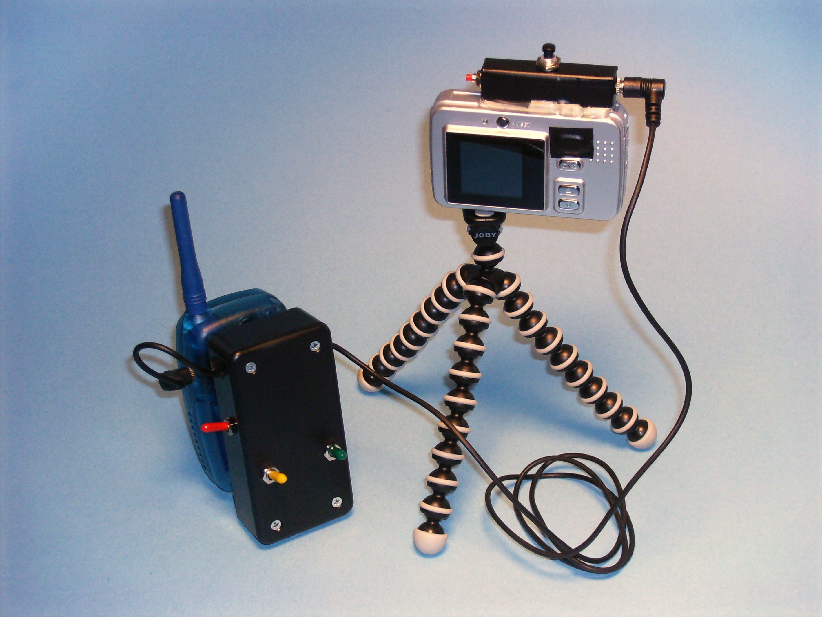
A few years ago, I was hiking with a friend along the ridge at Crater Lake in Oregon, and I saw a great spot for us to pose for a picture, on a cliff overlooking the lake. Unfortunately, the perfect place from which to take that picture was 250 yards away, over treacherous terrain. There was no way I could cover that distance in the 10 seconds allotted by my camera’s timer. So I stayed with the camera and sent my friend ahead to pose on the cliff alone. I was right, it was a great shot, but I was sorry we couldn’t both be in it. This gave me the idea to create a camera remote with enough range to let me take more interesting, adventuresome shots than the standard timer or short-range remote would allow. It occurred to me that a handheld radio could be used as a remote control, enabling me to set up the camera in advance, and then go pose for an “action shot” anywhere in the camera’s field of view. I could then trigger the camera with the radio.

Project Steps

Open up the camera.

Open the camera and remove the circuit board; I used a scrap of masking tape to secure the camera’s display. Find the on/off and shutter buttons on the circuit board.

This camera’s buttons consist of a central disk surrounded by an outer ring. A small metal dome sits on the ring, and pushing the button flattens the dome, bringing its center down on the disk, which closes the circuit.

CAUTION: Watch out for the camera’s flash circuitry; it can give you a shock even after the batteries are removed!

Test the camera buttons.

The camera’s circuit uses pull-down type buttons. When the button is not being pushed, the contact is kept high internally; when the button is pushed, the contact is shorted to ground. This may sound backward, but it makes the camera’s circuit more efficient and less susceptible to stray signals.

Set up the multimeter as a continuity tester, and connect one lead to the camera’s ground. Then use the other lead to test the button’s inner disk and outer ring. For this camera, the meter shows continuity between the inner disk and ground. This indicates that connecting the outer ring to ground signals a button push.

Mod the camera buttons.

Solder a wire to the outer ring. Now the camera will register the on/off button as being pushed when this wire is grounded. Do the same to the shutter button. Put hot glue on each contact to secure the wire.

Finally, solder a third lead to the ground side of the battery pack. Now you can take a picture by shorting the shutter lead to ground!

Discard the on/off and shutter buttons, and reassemble the camera with the 3 leads extending through the shutter button’s original hole.

Add the control jack and new push buttons.

Solder the 3 leads to a stereo jack so that the camera’s buttons can be hooked to the controller using a stereo plug. Then solder momentary push buttons between each button lead (on/off and shutter) and ground, so that the camera can still be used by hand.

Make a paper mock-up of the custom enclosure, then cut and bend the metal sheet to create the enclosure. Cut holes in the enclosure, mount the buttons and jack, and hot-glue the assembly to the camera body.

Mod the radio’s call button with new leads and jack.

The radio mod is similar, but you’ll tie in to different parts of the circuit. Remove the cover and find convenient contacts for ground and for the speaker’s signal wire, which is usually red. If it’s not, just use a continuity tester to find the speaker wire that’s not grounded.

Find the contacts for the radio’s call button (not the push-to-talk switch, but the button that sends the radio’s page tone). Solder leads to the ungrounded side of this button, the speaker signal contact, and ground (I took it from the LCD housing). Secure all contacts with glue.

Attach the 3 leads to a 1/8″ stereo jack, connecting speaker to tip, call to ring, and ground to sleeve. Reassemble the radio. If you can’t fit the jack inside the radio, glue it to the outside.

Assemble the time-delay controller circuit.

Following the schematic, mock up the arrangement of the components in the project enclosure, and make holes for the switches and wires. You’ll need to trim the project board and the inside of the enclosure to make everything fit.

The control circuit is built around a BASIC Stamp microcontroller, which has 8 input/output pins. The mini project board holds the parts in place, and wires are used to solder them together. Mount the microcontroller in the SIP socket so that it won’t be damaged by the heat of soldering (first trim away the SIP’s 2 extra holes).

Using the wires from the radio’s stereo plug, connect the radio’s ground to the microcontroller’s ground pin (VSS) and to the negative side of the 9V battery, then connect the microcontroller’s VIN lead to the positive side of the battery. Connect the VSS, PCO, and PIC pins to the 3-pin header so that you can download the control program to the BASIC Stamp.

Connect P0 (on lead 7) to VDD (+5V) via the 10kW resistor, then connect it to the 2N2222 transistor’s collector. Connect the transistor’s emitter to ground, and its base to the speaker’s output signal. When no current flows though the transistor, the resistor holds P0 high. But when the radio’s speaker applies a signal to the base, the transistor acts as a short and pulls P0 low.

Connect P1 to the radio’s call button so the controller can send an “acknowledge” tone by pulling the call button low. Pins 2 and 3 control relays that can turn the camera on or off and take a picture. Remember to pull the stereo wires through the holes in the enclosure before soldering!

Mount the controller and switches in the enclosure box.

After the circuit is assembled, put rubber feet on the bottom of the project board and hot-glue it into the enclosure. Then install the switches.

I used a DPDT for the microcontroller’s power and to disconnect the radio’s call button from P1 when the controller is off. I also used an SPDT switch to disconnect the transistor’s base from the speaker, and ground it instead, when I don’t want the controller to detect a signal. Then the SPST switch can disconnect the camera’s ground from the relays when I don’t want the controller to be able to take a picture. These last 2 switches aren’t needed, but they can be handy when troubleshooting.

Program the microcontroller.

Connect the serial adapter to the 3-pin header (shown at right), and use a BASIC Stamp editor (free at http://www.parallax.com) to write and download the microcontroller’s code (from http://www.makezine.com/15/diyimaging_re…). Be sure that the “<<” symbol on the adapter lines up with the grounded Vss pin.

Use a scrap of foam to hold the battery in place, and seal the enclosure.

My radio has a detachable belt clip, which I hot-glued to the enclosure. I added a Gorillapod tripod, and I’m all set!

Go long!

To take your long-distance self-portrait, aim the camera and turn on the controller and its radio. Then take a second radio, tuned to the same channel, and go get into the frame.

When you’re in position, press the call button. Once you hear the acknowledgment tone, you’ll have about 8 seconds before the picture is taken. A second tone will let you know when the cycle is complete.

If you plan to leave the setup unattended for a while, add a note with an explanation and a phone number, so that no one calls in the bomb squad!

Conclusion

To reassemble your device, follow these instructions in reverse order.

This project first appeared in MAKE Volume 15.

Related Posts on Make: Online:

Flashback: 2-Mile Camera Remote

http://blog.makezine.com/archive/2010/03...

Weekend Project: 2-Mile Camera Remote

http://blog.makezine.com/archive/2010/04...