The last couple of years have seen an explosion in home fabrication, with fantastic projects like RepRap and Fab@Home really helping to bring the open source community together. Unfortunately, 3D scanning — in many ways the flipside of the home fabrication coin — seems to have fallen by the wayside.
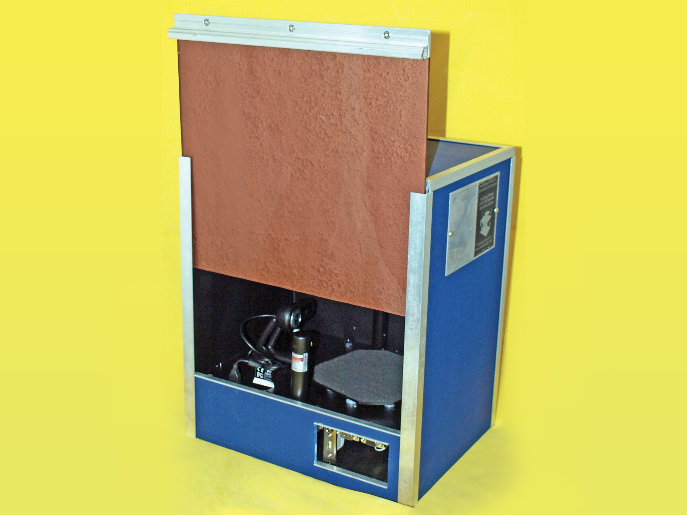
I decided to start the 3D scanning ball rolling by creating the SplineScan computer-controlled turntable. The turntable uses a gearbox for precise positioning, and has fixings for lasers, lights, and cameras. The obvious use of the turntable is for 3D scanning, although it can be adapted very easily to rotate objects for accurate photography or interactive display.
I’m currently using the turntable to archive and measure ancient artifacts as part of my Ph.D. studies (
http://www.mara-3d.org
), and I have to say that I’m very happy with the results so far.
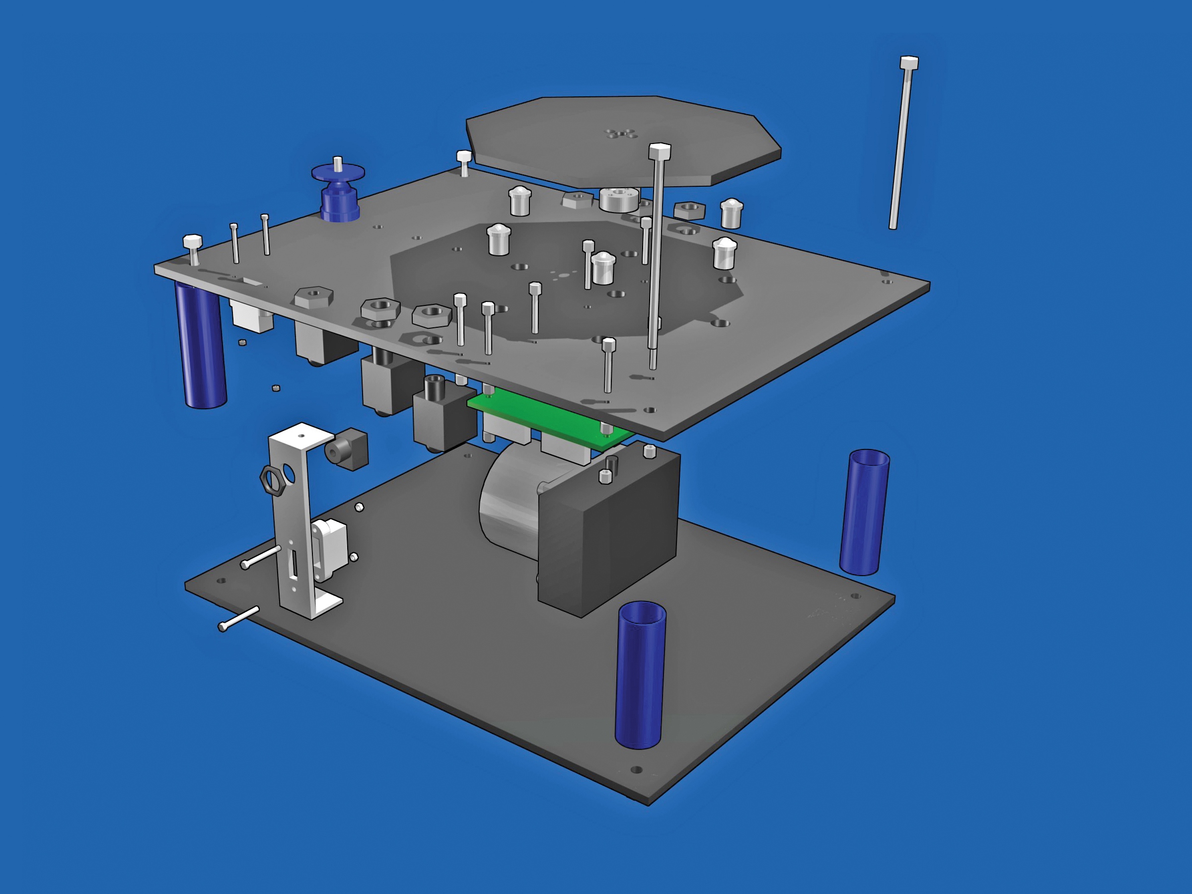
The parts list might look a bit daunting, but the project is not difficult to make. The scanner itself consists of 3 main parts:
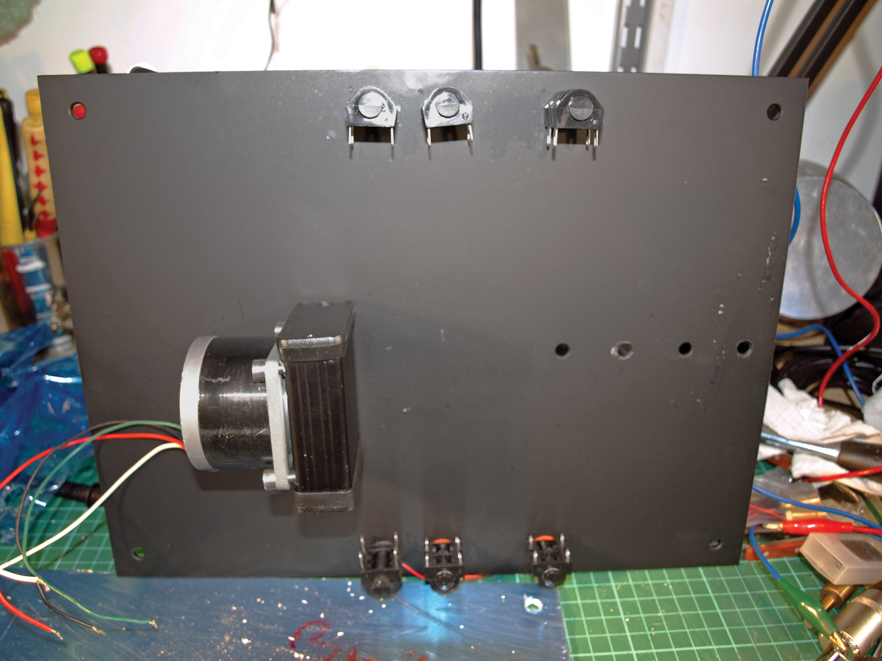
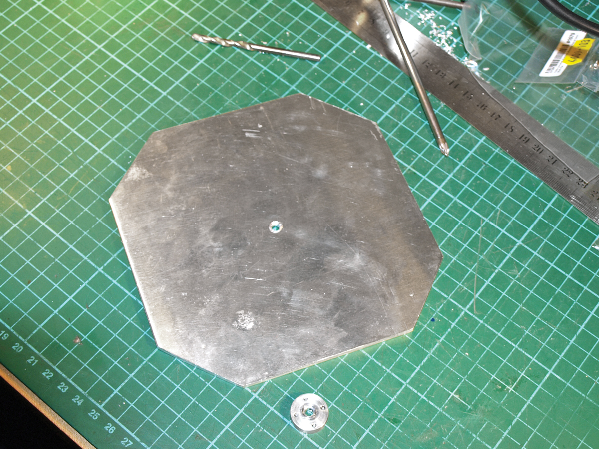
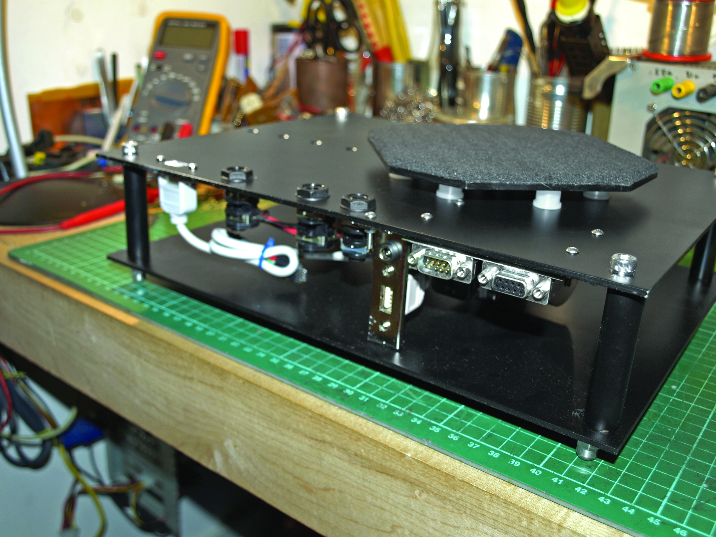
Chassis This is the backbone of the scanner. Everything fits onto the chassis, and it needs to be rigid enough to withstand the weight of all the other components, and whatever you intend to put onto the turntable.
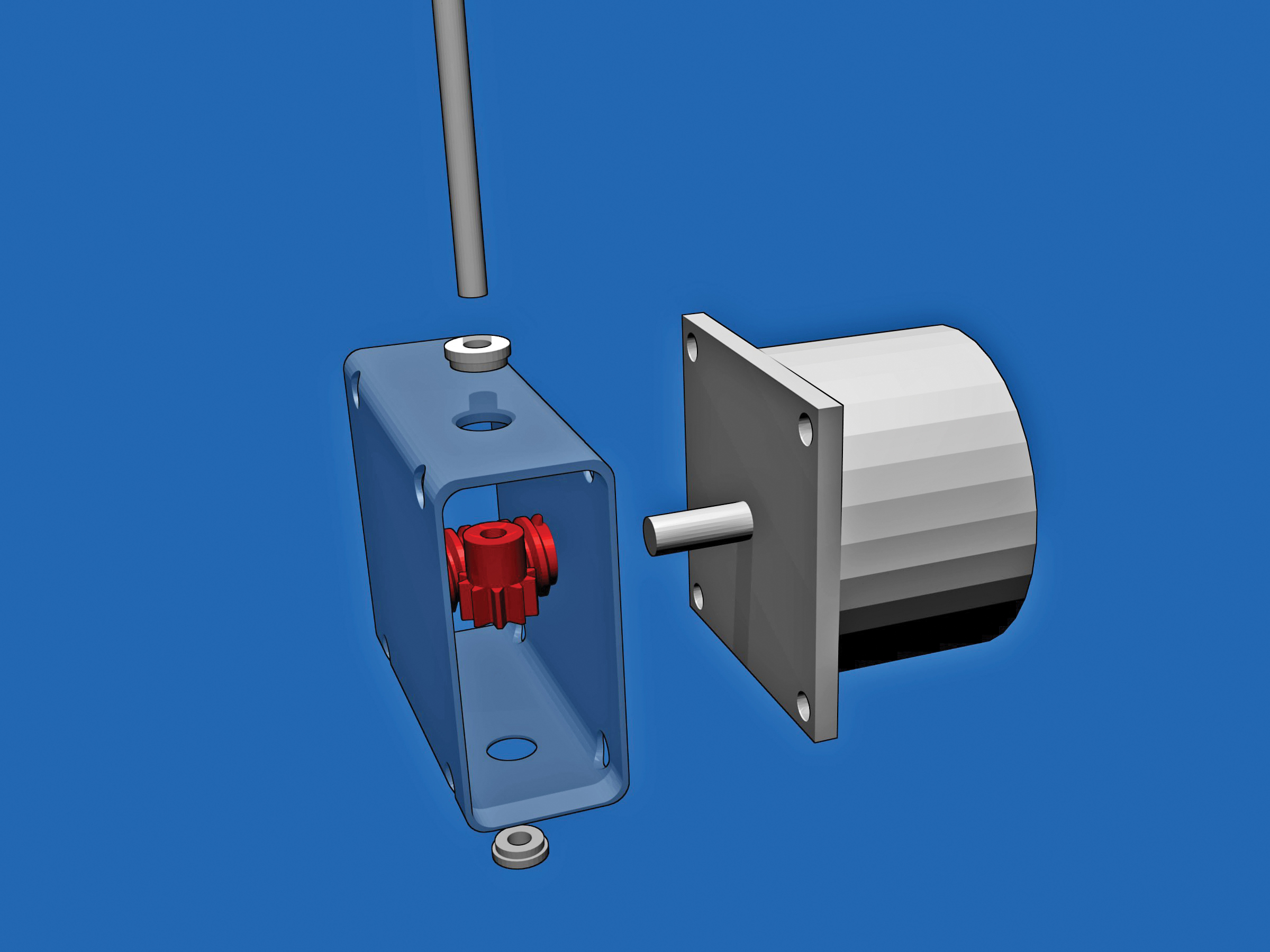
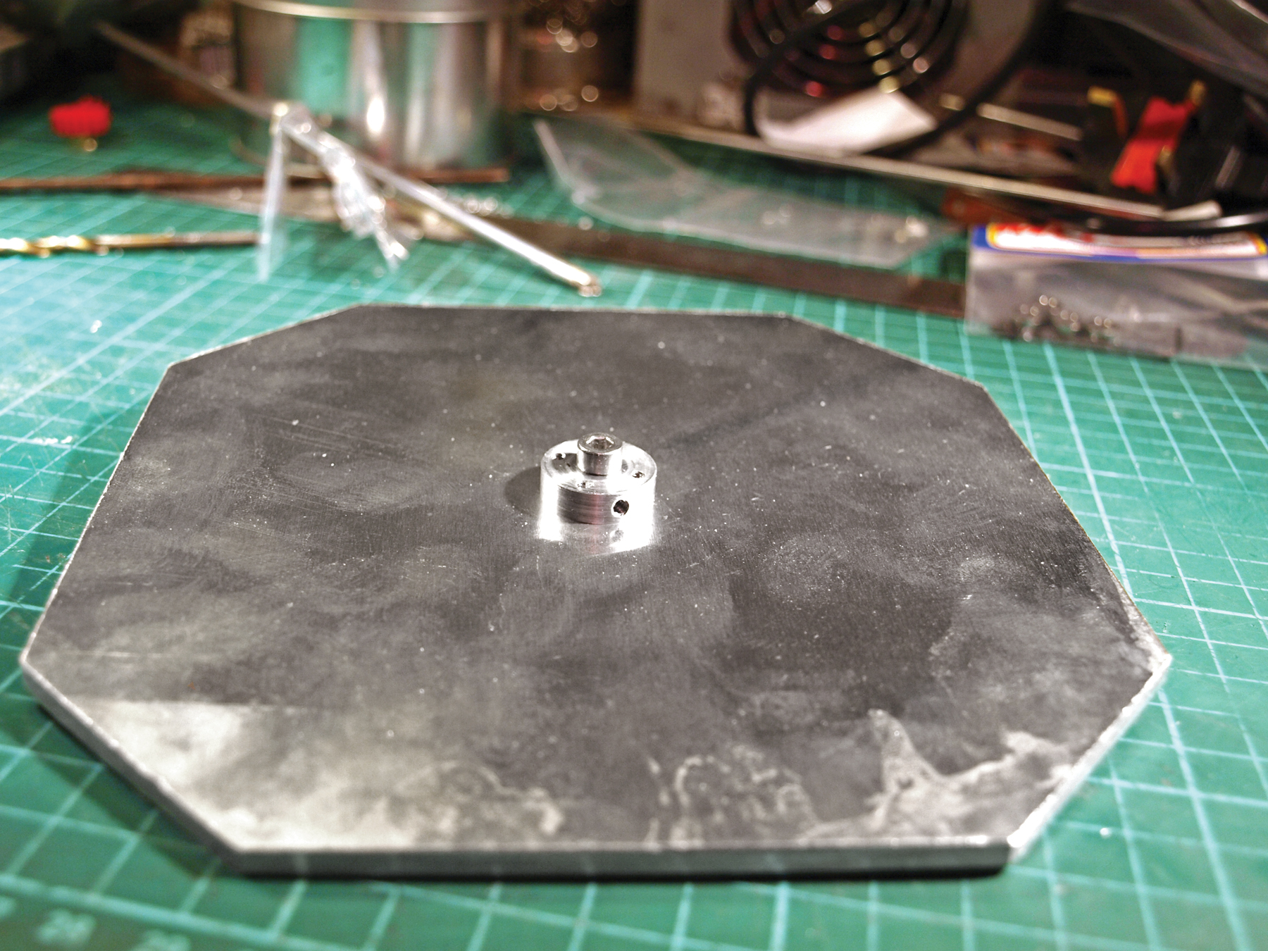
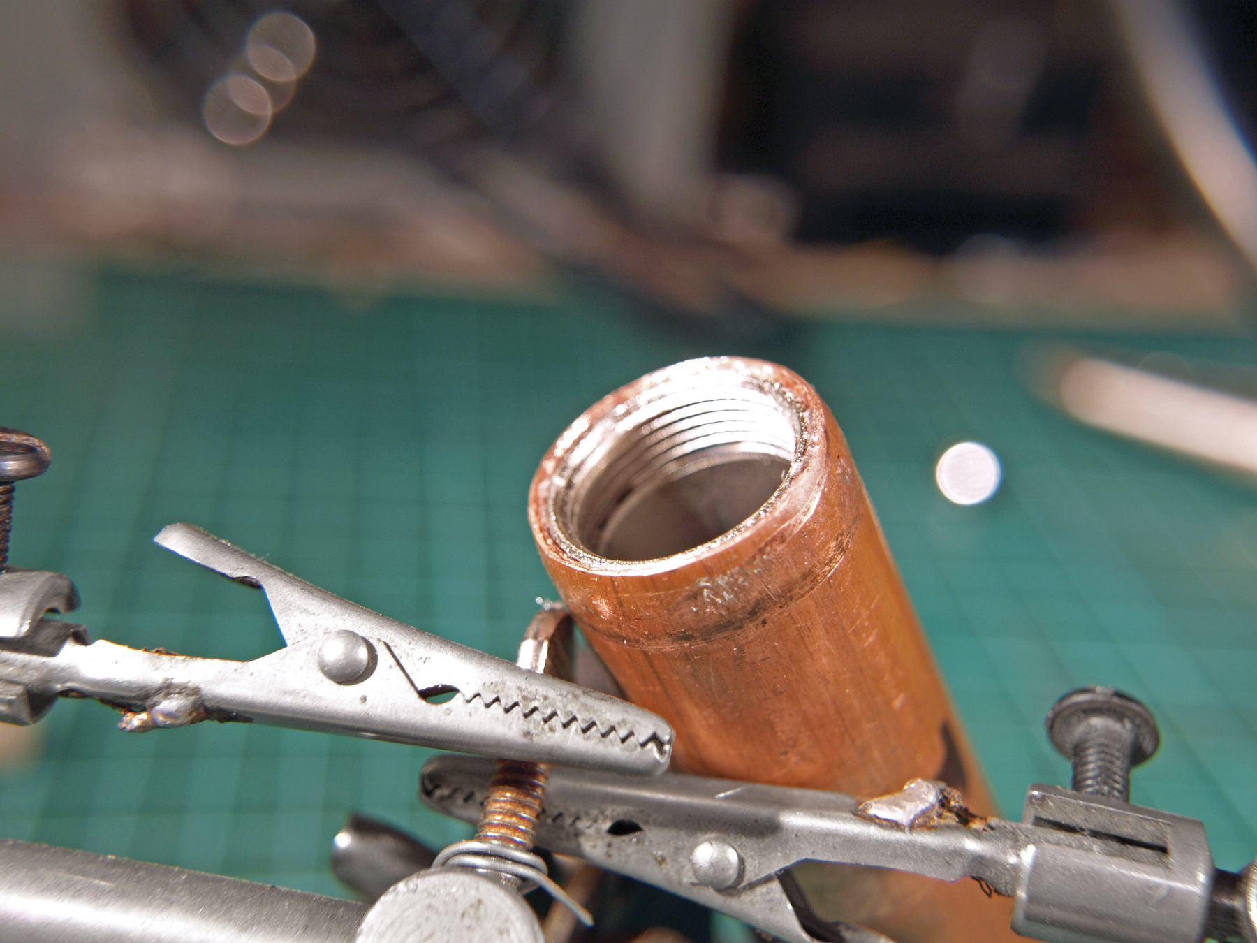
Gearbox This part takes the turning force of the stepper motor and turns it into something more suitable for our needs. It’s a simple design with only a few components.
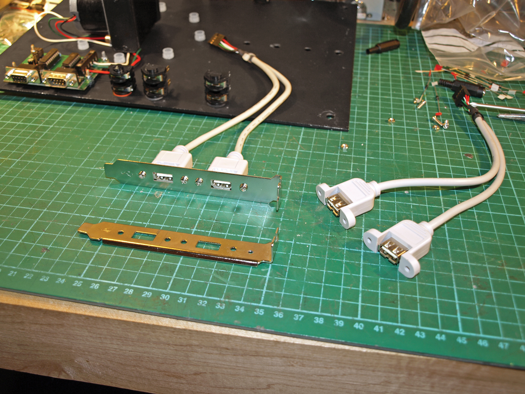
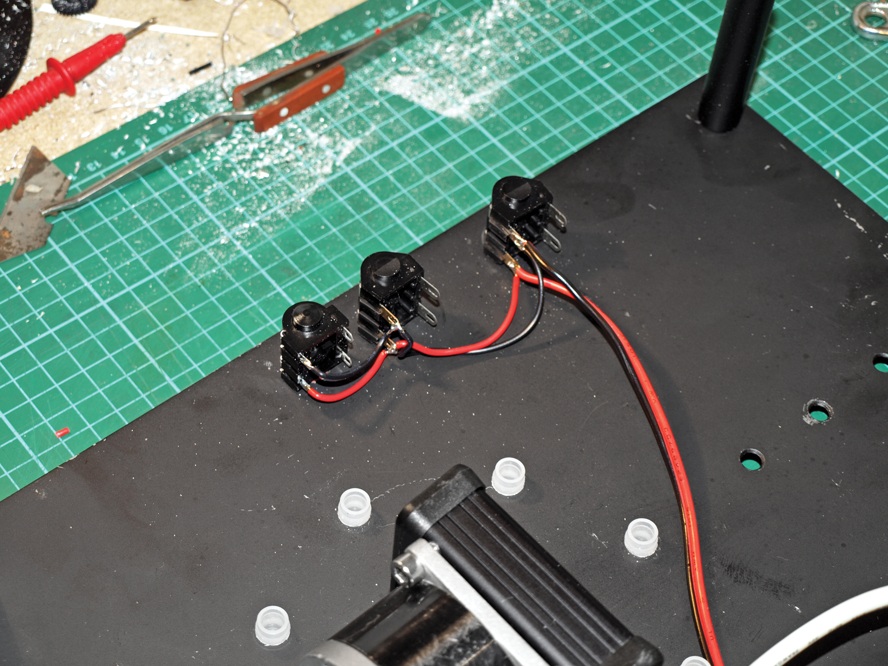
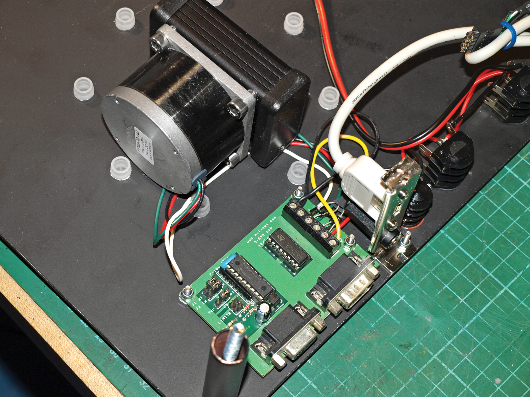
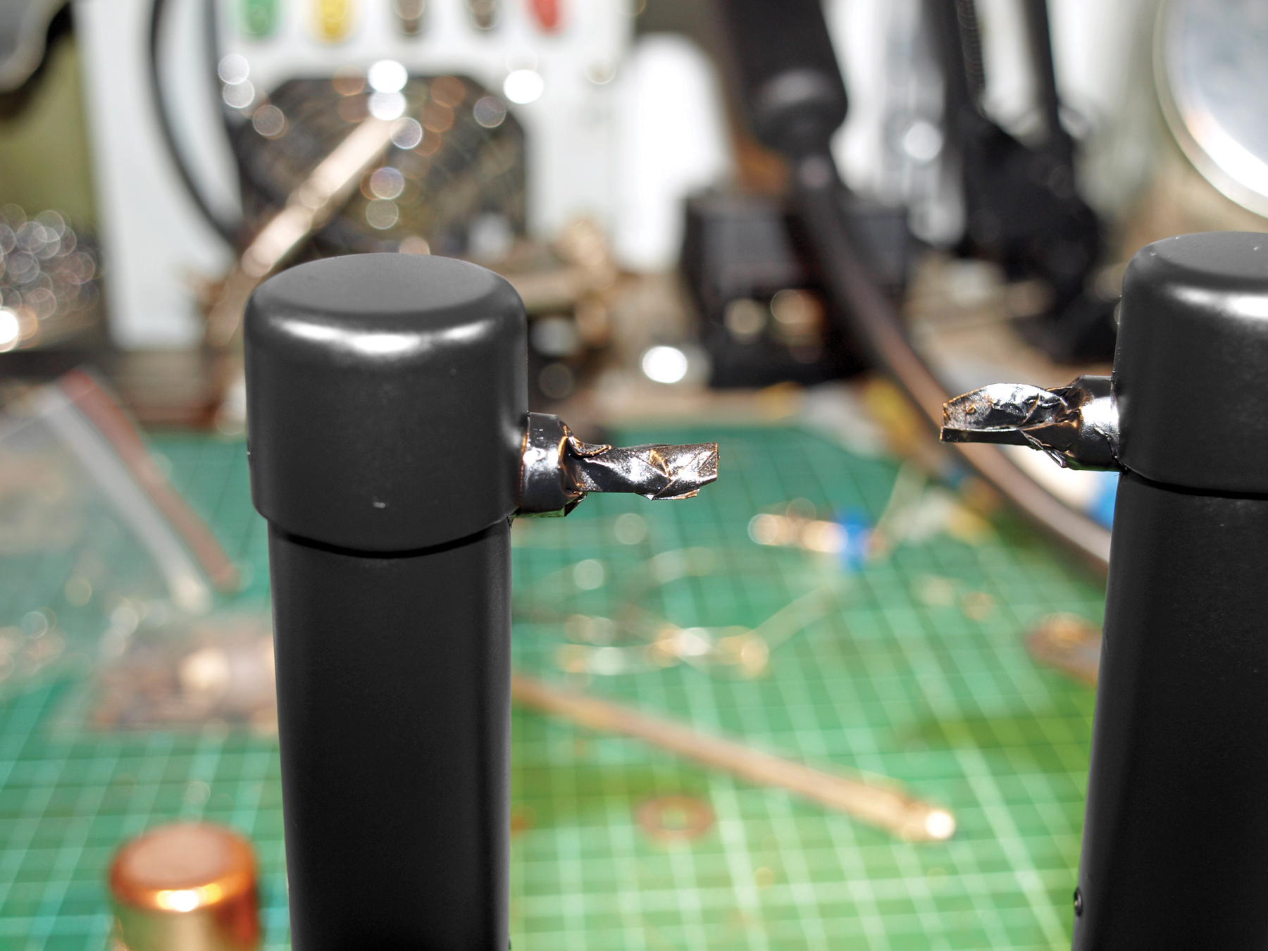
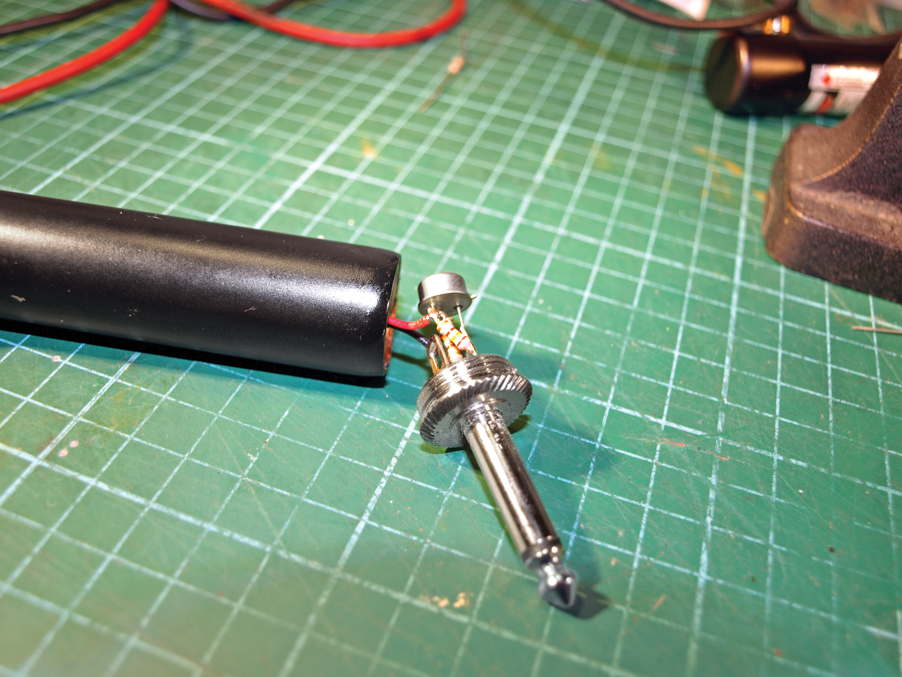
Electronics The brains and nerves of the scanner allow you control the turntable from your computer. The wiring is not difficult, and only limited soldering knowledge is required.
Steps
Step #1: Make the chassis.
Next


- Drill 4mm holes in the corners of the top and bottom plates, to accept the 65mm bolts that hold the chassis together. The 6 larger holes along the longest sides of the top plate are for the ¼" audio jacks. The outer diameter of the jack may vary depending on the brand you use.
- Use the exploded parts diagram and the template to decide on the hole sizes for the other parts of the chassis. Hole sizes will vary depending on product brands, and the best rule (after "measure twice, cut once") is to start small and drill bigger if need be.
- The small oblong marked on the top template is just a guideline for positioning the USB socket. The best source of USB sockets is a computer port extender that fits inside your computer and connects to the motherboard . Most computer shops have these on the shelf, but the design isn’t standard and the mounting holes can be in any position. If you want to fit your USB socket to the chassis, now’s a good time to mark and drill the holes using your socket as a template.
- The 2 aluminum plates are held together by 75mm M4 bolts and spaced apart by bits of copper (or plastic) pipe. The exact diameter of the pipe is not important. Cut four 65mm lengths of pipe and put one at each corner of the top and bottom plates. Feed the bolts through the corner holes in the top and bottom plates, and secure them temporarily with a nut. Make sure everything lines up correctly, and then disassemble the parts again.
- Now that all the holes are drilled, you can apply any finishing touches, like painting the copper and aluminum, and polishing any plastics.
- The turntable is supported by 6 plastic ball casters, which can be pushed into place at this stage. These should be a tight fit, but a little glue won’t do any harm.
- Install the six ¼" jacks, which go down both sides of the top plate; these will let you use 2 laser modules in various positions. With that done, you can turn your attention to the gearbox and motor.
Conclusion
This project first appeared in MAKE Volume 21, page 54
Related Posts on Make: Online:
Handheld 3D Scanner
http://blog.makezine.com/archive/2008/02...
3D Scanning with a Web Cam and Projector


