NOTE: This project is under construction! It’s very, very rough right now.

This project will require a 3D printer such as a MakerBot. You can also use a service such as Shapeways to have the files printed for you.

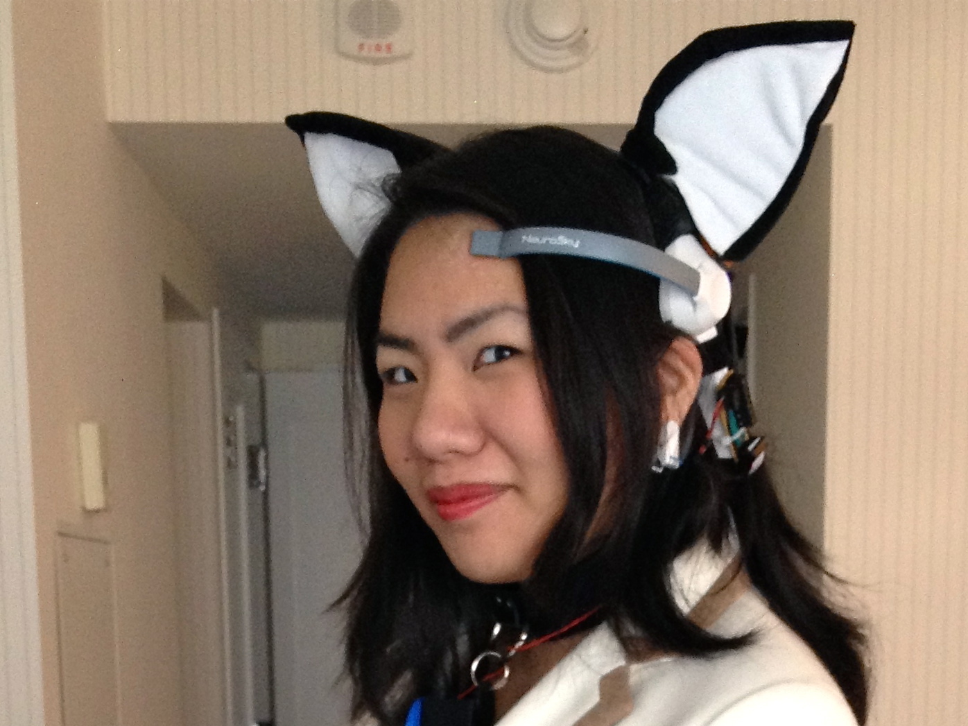
You’ll be assembling a mechanical set of ears based on servo motors, programming an arduino and tuning their movement, modifying an EEG headset to communicate with the arduino, and making an enclosure for the electronics.

Printable files and a part list for this project are available on Thingiverse. Code is available on github.

Project Steps

Print and compile plastic parts and electronics

Print the plastic parts (available on the Thingiverse page), using a Makerbot or other 3D printer. If you don’t have a 3D printer, you can use an online service such as Shapeways or Ponoko.

Print the servo mounts first and keep them together: the ear shells are harder to print, and you don’t need them immediately.

Assemble and mount servos on headset

Pull out your four micro servos and arrange them into two pairs.

Make certain to hang on to the little baggie with the white “servo horns” and the screws in them: they’re important.

Take a pair of small zip ties and attach them together into a loop, and hook the pair of servos for the left ear together.

Take care to route the servo wires as shown, and hold them in place with the zip ties. Add a second pair of small zip ties to finish assembling the left servo pair.

Assemble the right servo pair as a mirror of the left servo pair.

This is a great time to use a paint marker or label maker to label the servo lines.

Zip tie the servos together.

Lay the servo wires as shown.

Take a pair of small zip ties and attach them together in a loop, and slide them over the servos so that it sits vertically against the two servo bodies.

Ah, !*&^ it. Just use 3M double-sided tape.

Take the biggest servo horn and gently press it onto the “left pan” servo, then rotate it back and forth until you find the midpoint of the servo’s turning radius. Detach the horn (but be careful not to rotate the servo).

The “left rear” servo mount has a depression for the servo horn. Fit the horn into that depression, and hold it in place with a bit of tape for now.

Slide the left rear servo mount onto the headset (it fits on the back of the big electrode hinge thing) and hold it there with one hand.

Carefully, fit the “left pan” servo onto the horn as shown: it should be at about a 30-45° angle to the front of the headset.

Take the servo mount off the headset, and use a small philips-head screwdriver and one of the provided screws to attach the left pan servo to the left rear servo mount.

Repeat the process for the right rear servo mount. Make certain to use the “right pan” servo and mount it at a 30-45° angle opposite the left servo pair.

Now it’s time to attach the servo mounts to the headset.

The left servo mount should slide together like puzzle pieces. Fit them together over the flat grey band of the headset, as shown, then slide down onto the left side.

Depending on your printer, the left servo mount may fit a bit loosely. I wrapped the white plastic of the headset with a single layer of electrical tape to add some friction.

The right servo mount should fit tightly on the flat grey headset band. Slide it onto the right side of the band approximately 5 inches from the point where the grey band meets the right.

You’ll adjust the precise location of this ear later: since the headset expands to fit different size heads, you’ll need to tune it to fit.

Use ?mm M3 socket cap machine screws to attach the right servo mount to the headset.

You should have two pairs of servos mounted on the headset in a mirror configuration.

The “pan” servos should be attached to the mounts, and the “tilt” servos should be on the inside of the headset.

Assemble ears on headset

Attach the large servo horn to the left tilt servo, and rotate it back and forth, imagining that the short bars are the vertical axis of the ear.

Rotate the tilt servo all the way “back”, then about 15° forwards, and carefully detach the servo horn.

Place the servo horn in the depression in the left ear, and use some tape to keep it in place.

Carefully fit the left ear onto the left tilt servo so that it’s standing upright, and use the small philips screwdriver and one of the provided screws to attach the ear to the left tilt servo.

Magnetizing the screwdriver tip beforehand may help make this step less frustrating.

Repeat the process for the right ear and the right tilt servo.

Now that both ears are on the headset, it’s time to adjust the right ear’s position.

Put the headset on and look in the mirror. You want the ears to be symmetrical. If they aren’t mark the headset with a pencil where the edge of the right ear servo mount should be.

Then take the ears off and loosen the mount, slide it into place, and tighten again. Repeat as necessary.

Put the ears on the styrofoam head and zip-tie the cables together, and run them back to the rear of the headset, as shown.

Attach servo extension cables to the ear servos.

Remember to label the servo extension cables, too: left pan, left tilt, right pan, right tilt.

Success! You should have a pair of ears on a foam head, with servo extension cables running away, ready to be controlled by an arduino.

(Optional) This is an excellent time to start making fur or fabric covers for the ears, now that they’re on the headset.

Control and tune ears with arduino

Before you try and control these ears with your brain waves, you’ll want to tune the ears’ position and movement.

This project is controlled by an arduino nano. I also have an arduino uno, which I used to tune the movement, for reasons of convenience. You can easily substitute a nano for the uno in the reference pictures.

Connect a 10K-ohm potentiometer to analog pin 0 of the arduino. This will stand in for the “attention” variable which will later be provided by the MindWave headset.

Connect the 4-AA battery to the second power and ground rail of the breadboard, then run a wire bridging that ground rail to the arduino’s ground.

If the AA pack has a switch, make certain it is off! Otherwise, disconnect the power line for now.

Clip four sets of 3-pin male breakaway headers, and use needle-nose pliers to push the plastic into the center.

Put the 3-pin headers on the breadboard, and run ground and power from the AA battery pack to them, as shown.

Connect jumper wires from pins 3,4,5, and 6 to the third pins on the headers.

Now, attach the servo extension cables to the 3-pin headers, in the following order (starting at arduino pin 3 and going up to 6): right tilt, right pan, left tilt, left pan

Make certain that the orange wire on the servo extension cables is on the pin that runs to the arduino’s digital pins, and that the red wire connects to power. If you accidentally connect power to the orange (control) pin on the servo, you will almost certainly fry your servo.

Download the MindWave Cat Ears arduino code from github, and upload the MindWave_Cat_Ear_Tune sketch to the arduino.

Make certain your Arduino is connected to your computer through USB, and open the Serial Monitor in the Arduino IDE.

In the lower right corner of the Arduino Serial Monitor, use the pop-up menu to select “115200 baud”. You’re ready to tune the ears!

In a previous step, you switched off (or disconnected) the 4-AA battery pack. Switch it on again (or re-connect it), and the ears should jump to position.

The potentiometer on the board controls the numbers streaming by in the Serial Monitor: turn it back and forth and watch how it affects the first value, which is “attention”. The other values are the positions of all four servos, in Microseconds. These are the values we need to tune.

The ears are probably a bit lopsided. Twist the “attention” knob back and forth for a bit to get a feel for their range of motion.

Now, scrub the attention knob all the way to 0. The ears should be symmetrical. When attention is low, they point “out” and to the sides, and tilt down to nearly flat.

Use a notebook and write down the values for lp, lt, rt, and rt. Those are the minimums right now.

Now scrub the attention knob all the way up to 100. The ears are supposed to be tilted up and facing forwards, symmetrically, like a fascinated cat. Mark down the values for lp, lt, rp, and rt again. Those are the maximum values.

Notice how lp‘s “minimum” value is higher than its “maximum,” but rp is the opposite? That’s because the servos are moving in a mirror image configuration.

This is where intuition and trial and error come into play. You need to adjust the minimum and maximum values for your ears so that they look and move right. (For example, If the left pan servo’s range is too far counter-clockwise, adjust its minimum and maximum values by reducing them.)

Try to make the difference between min and max the same on both sides: if the left pan servo moves a total of 300 microseconds, make certain the right pan servo also moves 300 microseconds. This will help synchronize the ear movements.

Tilt is easier to tune than pan. Try to get both ears standing up and lying down correctly first, then adjust how they move side to side.

You’ll know you’re done when the ears sweep up to face forwards like an excited cat at attention 100, and droop down and to the side at attention 0.

Write down (or copy and paste into a text file) the servo values you’ve found for minimum and maximum. You’ll need to plug those into the full Cat Ears sketch next.

Open the MindWave_Cat_Ears.pde sketch in the Arduino IDE and paste your minimum and maximum values for all four servos into the variable definitions.

Conclusion

Once you've completed this guide, you should have a pair of ears on a MindWave Headset, with an arduino board on your desk controlling their movement according to your brain waves.

The next thing to do is to assemble the control circuit into an enclosure, manage the cables, and make the whole unit wearable. That's a design challenge I'm still working to overcome, so I'm interested to see what solutions you come up with.

Good luck!