


Projects from Make: Magazine
Arduino Theremin
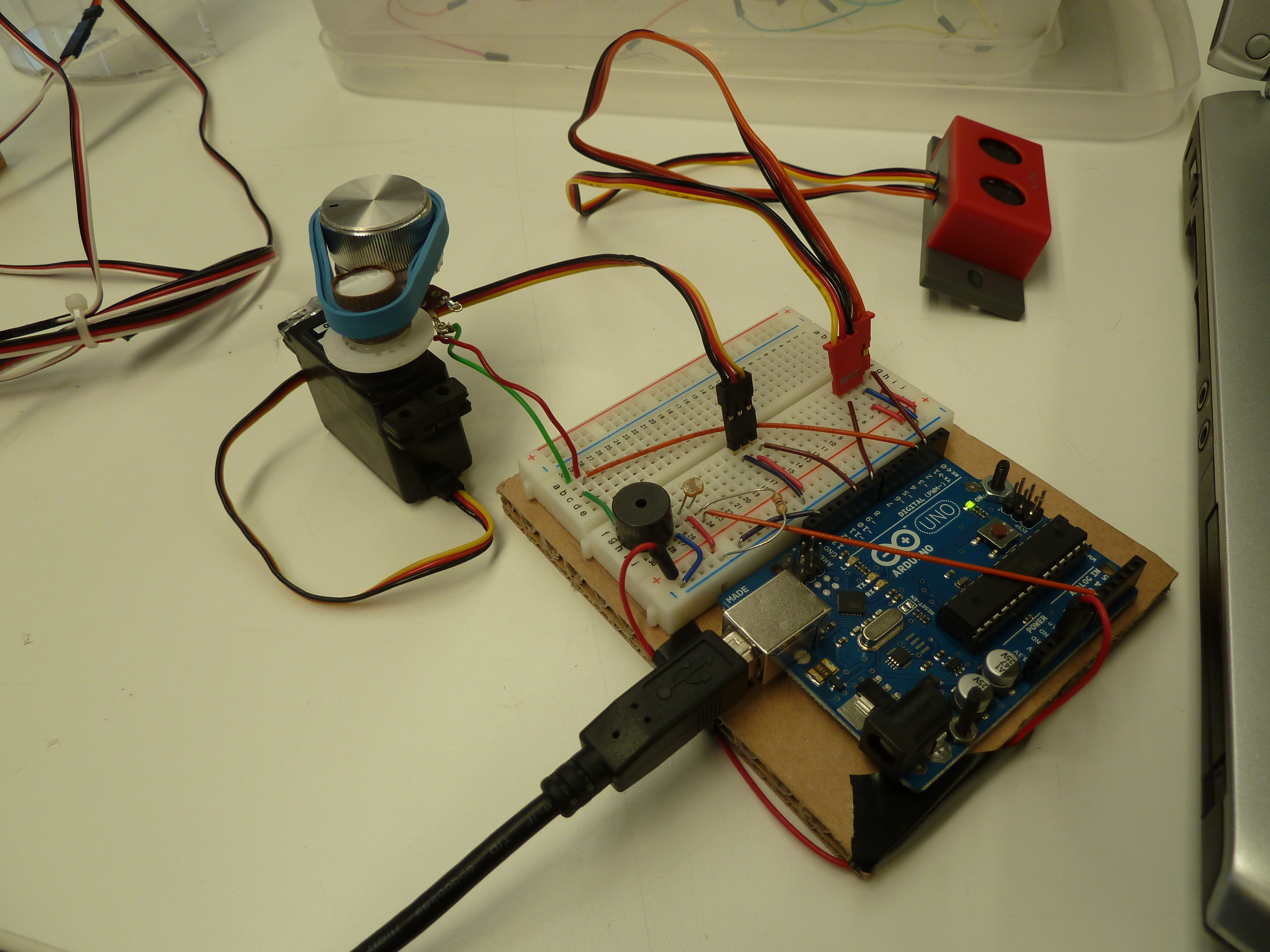
A theremin-like device to control the pitch and volume of a musical note. It utilizes a photo-resistor to control the pitch, and an ultrasonic sensor to control a servo controlling a potentiometer controlling the volume.

Decide to Tackle this project.
If you want to make music, then this project is for you; move on to step 2.


Solder Wires onto the potentiometer. I used red for the audio voltage in on the left and green for the voltage out in the center.
I initially soldered on a black wire on the third pin, but removed it as it was redundant.
Hot glue the Dowel onto the servo, centered, and then super glue the sandpaper to the dowel to provide a traction for the rubber band.
Find a rubber band, preferably wide, that can be used to transfer the servo motion to the potentiometer.
Hot glue the potentiometer in place. Don’t be sparing with the hot glue, as it is not terribly strong.
Turn both the potentiometer and servo all the way to the left and link them together with the rubber band. I had to use several as the servo shifted while the glue was cooling.


Wire that Arduino.
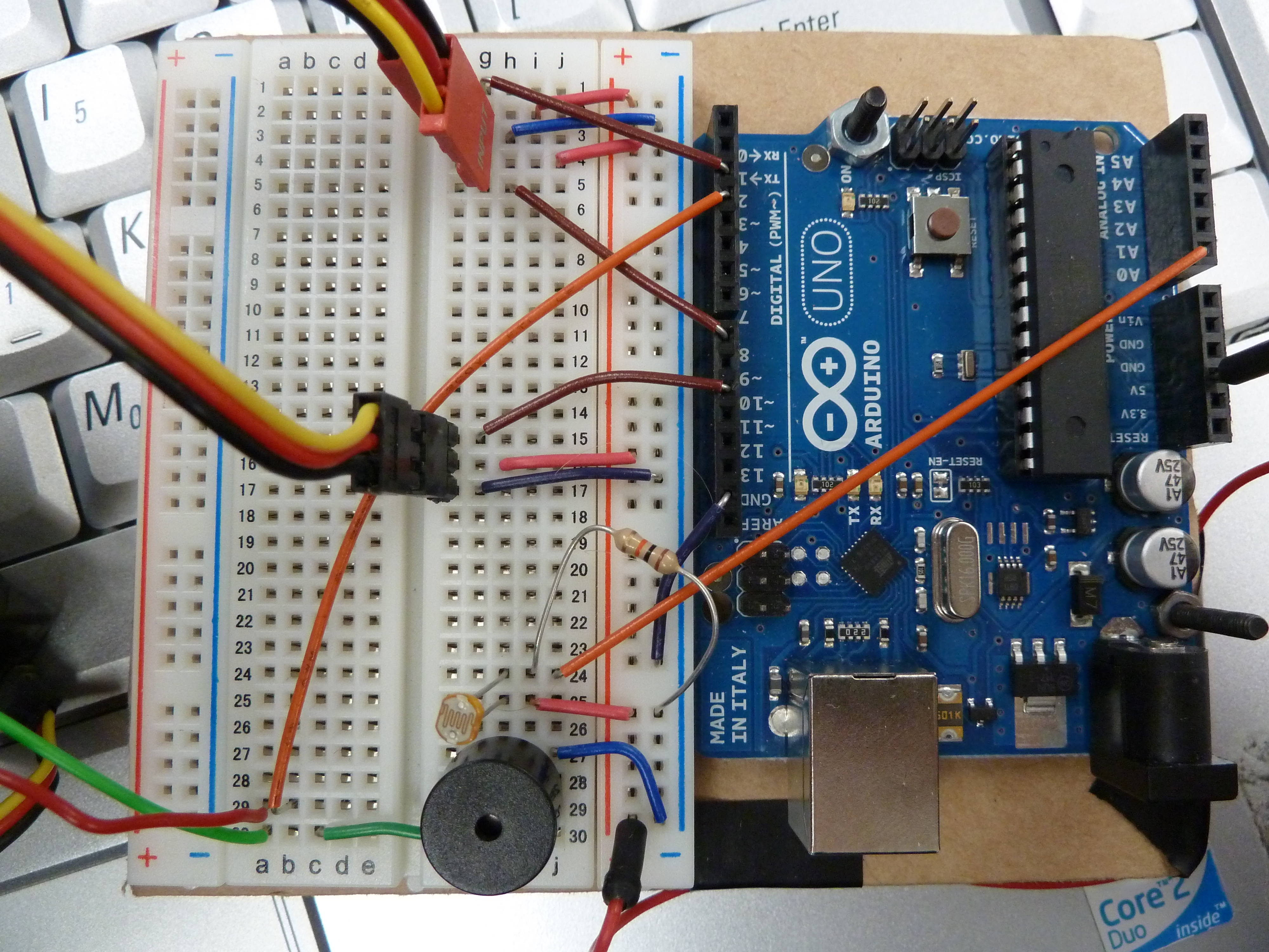
Supply +5V to the power rail on the breadboard, and then to each ultrasonic power pin, the servo power pin, and the photo-resistor.
Supply GND to the GND rail on the breadboard, and then to each ultrasonic ground pin, the servo ground pin, and the piezo buzzer ground pin.
I use analog 0 for the photo-resistor output, digital 10 for the servo, digital 2 for the ultrasonic output, and digital 8 for the ultrasonic input
Use a 10k Ohm resistor as a pull-down for the photo-resistor, by connecting it to GND and analog 0, or whatever analog pin you end up connecting the photo-resistor to.

Now it is time to code the Arduino.
See attached file, theremin.pdf for the code.
The volume should increase as your hand is moved closer to the Ultrasonic, so if else happens, simply reverse the mapping of the servo position.
Change the code from rad = map(dist, 8, 20, 0, 90); to rad = map(dist, 8, 20, 90, 0);


