Do your co-workers talk too long at meetings? Do you use a ‘talking stick’ but there’s always that one person that never gives it up? Do you wish you could drown out pols during debates when their allotted time is up?

Bleeping Talk Timer is a simple countdown timer built using analog logic that triggers a piezo alarm when the time is up. No Arduinos here! No digital logic is involved. Just a simple circuit built with common components that keeps track of time. The circuit is built around the venerable 555 timer IC, a little chip that continues to fascinate me with its design, engineering, and applications, from LDR theremins to motor control to countdown timers. It’s estimated that a billion 555s are manufactured every year.

btt_schematic

Ubiquitous as it is, note that this project does not use the low-power CMOS 555 “TLC” variant. The LM555 variant from RadioShack is capable of 18V of maximum input voltage, and we’ll be plugging a 9V battery into this circuit. Low-power 555s are better suited for applications where prolonged battery life or finer precision are required.

You can read up on the theory, background, and fundamentals of the 555 timer in Charles Platt’s Make: Electronics book, pp. 150–161, available from the Maker Shed and from RadioShack stores. Electronics Club also has a great run-down on the operations and applications of 555 timers.

Inside the 555 timer, from Charles Platt's book Make: Electronics, p. 158.
Inside the 555 timer, from Charles Platt’s book Make: Electronics, p. 158.

Thus, to best explore and understand the operation of this circuit I highly recommend you breadboard it first. Because this is a countdown timer circuit that actual timing will vary based on components used. The minimum and maximum settings of the timer are partially controlled by the linear-taper potentiometer. Because we’re not using pin 1 of the pot, there is no “0” time coordinate. The connections from pin 2, the wiper, and pin 3, with this configuration, effectively made my timer range from ~35 seconds to 5 minutes. In my experiments I found there was a +/- margin of error of 3% (due to power dissipation from the electrolytic cap); this could add or subtract as much as 9 seconds to the timing when the pot is turned entirely to pin 3. Although truth be told the timer was more ‘precise’ the longer the time set, and it consistently hit 5:00 exactly.

So you’ll want to play with your components, take notes, and build accordingly. Here’s a snapshot of my breadboard layout:

BTT_fritzing_illu_edit

I’ve color-coded the jumper connections, which I’ll go over in the project steps.

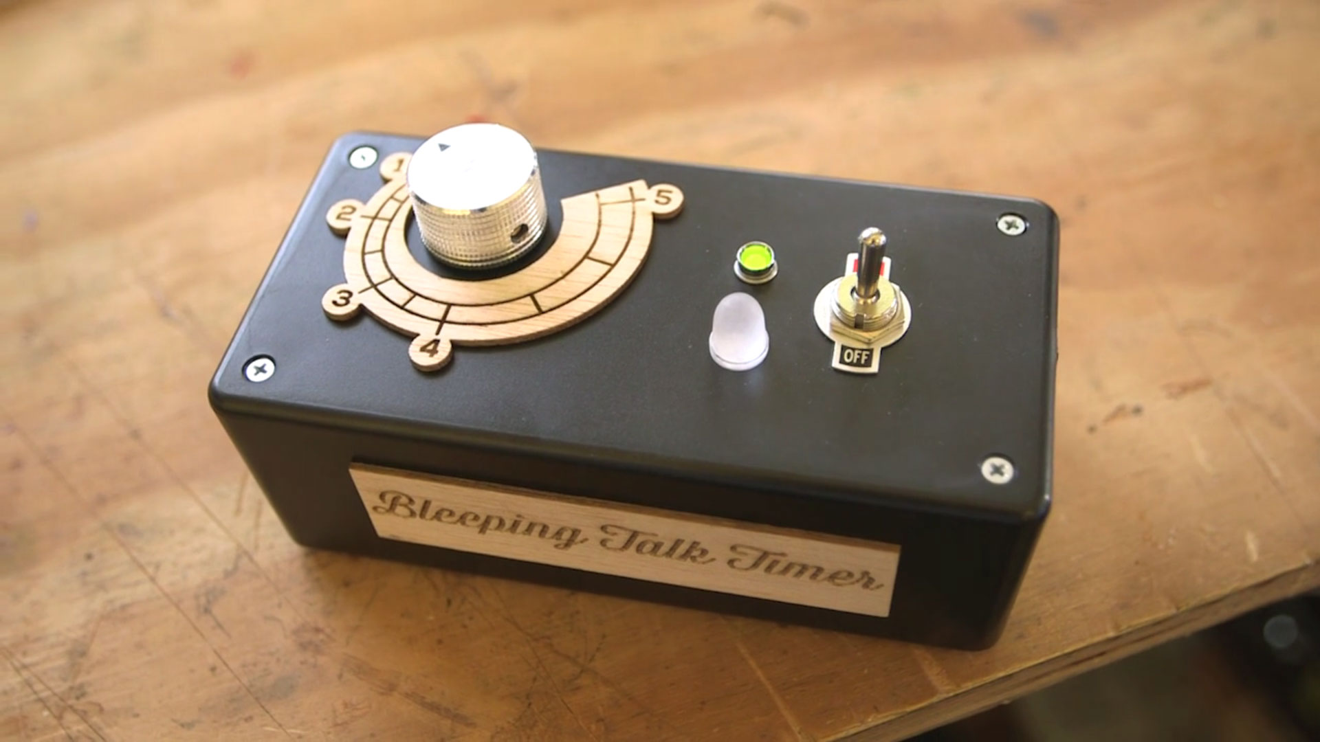
When the circuit is switched ON, the green LED will light up. When the countdown is complete, the green LED will switch off, the red LED will switch on, and the piezo buzzer will alarm! These two components will stay powered on until the circuit is switched OFF (or the battery dies). The piezo buzzer is loud, really loud. Annoyingly loud! 78dB loud :)

The video below shows the circuit in operation built into a project enclosure. Note this video is not real-time! I’ve purposefully clipped the video to show the LED-switching function (and I’ve considerately turned the audio off!):

OK let’s get building!

NOTE: I’m indebted to John Hewes at Electronics Club (formerly kpsec.freeuk.com) for use of this circuit, slightly modified for my components and design tweaks. His website has long been a valuable place to stop by to wrap my head around electronics theory and fundamentals. Thank you John!

Project Steps

Prepare your wares.

Layout shots not only look cool, they’re great for going over your parts before you begin building.

These parts are for the breadboard build only. Even though this is a breadboard phase, we’ll also be soldering some connections, so get your gun and solder ready!

NOTE: The leads of the ceramic disc capacitor pictured have already been clipped; typically those leads will be much longer.

Place the core components.

Note: these illustrations were made with Fritzing. I changed the ordering of the illustrated breadboard columns to conform to the real-world breadboard used. This is an unfortunate inconsistency between software and hardware. Keep this in mind if you use parts from other suppliers. Here, the columns are always indicated A–E and F–J from left to right.

Place the 555 over the breadboard’s trough with pin 1 aligning to row 10. The 8 pins of the 555 are read counter-clockwise from the top-left where the ‘dimple’ is located.

Place the three resistors: 470Ω connects E5 to E9; 150K connects I7 to I11; 33K connects I2 to I6. Resistors are not polarized, so you can place them either way.

Place the ceramic disc capacitor from C10 to C11; this component is also not polarized, and can be placed either way.

The LEDs and electrolytic cap are polarized, so be careful to place these components correctly! Place the green LED’s positive (+) lead (anode, long leg) in D9 and the LED’s negative (–) lead (cathode, short leg) in D10. Place the red LED’s + in H2 and its – in H3. Place the electrolytic cap’s positive lead (long leg, the side without the stripe) to J12 and its negative lead (side with the stripe) to J16.

Image 3 shows the completed layout. I “buffed” the 10mm red LED to give it a diffused look, using a rotary tool with a polishing bit.

Connect all the jumper wires.

Begin populating the breadboard with wires to jump all the connections. I got my wires from the jumper wire kit listed in the parts list; it comes with a brown wire that I’ve replaced here with a 22AWG black wire because the brown wire was just a little short. Use what works for you. I like color in my projects!

In image 2, the following jumps are listed from shortest to longest: Jump H11 to H12 (short yellow). Jump J2 to the power rail; jump J10 to the power rail (both orange). Jump C3 to C5 (blue). Jump A10 to the GND rail (grey). Jump A5 to A12 (white). Jump A11 to H6 (black). Jump C2 to H7 (green). Jump A13 to the power rail (red). Jump B10 to I16 (long yellow).

Image 3 shows all these connections placed — it looks cool!

Connect the potentiometer and the piezo.

Cut two 6″ lengths of 22AWG hookup wire and strip both ends. I pre-tin my wires before soldering them to components.

Solder one wire to pin 2 of the potentiometer. Solder the other wire to pin 3 of the pot. Slide a piece of heat-shrink tubing over each wire, covering the solder connection and terminal. Use a heat gun or other heat source to shrink the tubing.

Connect the pot’s pin 2 wire to D2 on the breadboard; connect pin 3’s wire to G2.

Connect the piezo buzzer’s black wire to E3, and its red wire to F3.

Solder the battery clip to the SPST switch.

Pre-tin the battery snap connector’s red and black wires. Slip a piece of heat-shrink tubing over the red wire. Thread the end of the red wire through one of the SPST switch connectors. Solder the wire to the connector.

Slide the heat-shrink tubing over the connection and use a heat gun to shrink it.

Connect the switch to the breadboard.

Cut another 6″ length of 22AWG hookup wire, and strip and pre-tin both ends. Connect one end to the other SPST switch connector. Solder in place. Slide a piece of heat shrink tubing over the connection and use a heat gun to shrink the tubing.

Connect the battery clip’s black wire to the ground rail of the breadboard. Connect the available red wire from the SPST switch to the power rail of the breadboard. Now you have a battery clip connected to both “throws” of the switch.

Images 2 and 3 show the breadboard layout (in lieu of a toggle switch, Fritzing uses a pushbutton SPST switch).

Time to test ... BLEEEEEEP!

Connect the 9V battery to the clip, and flip the switch! The green LED will light up. Now, patience, Padawan.

Depending on the position of the potentiometer, you will wait anywhere from ~35 seconds to 5 minutes before the circuit switch occurs: the green LED will switch off, at the same time the red LED will switch on and the piezo buzzer will alarm. It works!

Mess around the with the potentiometer to gauge the range of your timer. Take notes. Now let’s permanently solder the circuit to perfboard and put it all into an enclosure!

Prepare the perf board.

I wanted this project to be an easy translation from breadboard to perf board, so I chose this “experimenter” PCB, which you’ll notice has the same layout as the breadboard. That’s great!

Score and snap the perf board to size. I opted for 18 rows. This fell nicely between the outer rail jumper points, while adding a couple extra rows to play with if necessary.

If you don’t get a clean snap, use a rotary tool or file to grind down the excess perf board.

Prepare the enclosure.

The components fit well laid out left to right, as shown here: potentiometer, battery, then perf board circuit. (The pot pictured is a spare pot. I’ve always found it useful to keep similar parts available for layout purposes.)

That means the layout on top of the enclosure box will be knob, [space], red and green LEDs, and switch.

I used a pencil to mark the approximate locations, then I drilled a 3/8″ hole for the SPST switch, and 1/4″ holes for the pot shaft, green and red LEDs.

The pot’s shaft is not centered vertically on the box lid; I plan to address this with some sort of ‘sweeping’ dialplate to be designed later.

Now that we know where everything will live, let’s get soldering! (You’re about to make more than 50 solder connections, so take a break if you need, prepare yourself mentally, and get ready!)

Transfer the circuit to perf board.

Start by relabeling the perfboard A–E and F–J with a permanent marker. This will ensure all your connection points follow the same designation.

Solder the 8-pin IC socket into place, with its notch facing “north.” This will be your reference point for all other connections. Leave the actual 555 timer IC in the breadboard until the very end.

Transfer each of the components over from breadboard to perf board,

and solder them in place. Follow the same sequence you did before: resistors first, then capacitors, then jumper wires.

Then solder the off-board component leads: first the potentiometer’s 2 wires, then the piezo buzzer’s wires, then the black wire from the battery clip and loose red wire from the SPST switch. The layout matches the breadboard perfectly.

Wire the LEDs.

I trimmed the leads on my LEDs. I always trim the shorter leg first — that way I know which leg should be the shorter leg!

Cut and strip 2 lengths of black 22AWG wire and 2 lengths of red 22AWG wire. Around 6″ is plenty. Pre-tin all the ends — it really saves time and makes connections a cinch later!

Solder a black wire to each LED’s cathode, and a red wire to each anode.

Insulate and mount the LEDs.

For both LEDs, slide red heat-shrink tubing over the red wire and slide black heat-shrink tubing over the black wire. Use a heat gun to shrink the tubing.

Slide the LEDs into their respective holes in the enclosure lid. Fasten the green LED with the included nut using a pair of needlenose pliers. Squirt a bit of hot glue to hold the red LED and wires in place.

Solder the LEDs to the circuit board.

In my experience solid-core AWG hookup wire is quite unruly and stiff. I used a pair of helping hands to securely hold everything in place while I carefully routed the wires from the LEDs to their respective solder locations on the perf board.

Double-check your LED wires.

Triple-check your LED wires.

Solder the LED wires to their locations! Only solder one connection at a time if you’re hesitant or unsure.

Finally, with all the components and connections soldered to the PCB, take the 555 timer chip from the breadboard and insert it in the 8-pin socket. Test the circuit again before proceeding.

Yay, we’re done with soldering and it’s time to secure everything in place in the project box.

Mount the switch and circuit board.

The SPST switch has a top nut, an ON/OFF label plate, and a bottom nut. Remove the top nut and ON/OFF plate. Place the switch through its hole in the lid, slide the ON/OFF plate over it, peel the plastic backing off the plate, and secure the switch in place by tightening the top nut with a pair of pliers.

Place the circuit board in the enclosure as far to the right as possible. Use a pencil to mark the location of the board’s 2 mounting holes. Note the perf board is being placed upside-down from how we’ve been working heretofore, based on the orientation of the components and wire lengths.

Make an upside-down T with hot glue on the bottom of the enclosure, and press the perf board into place. Hold it there for a couple minutes while the glue cools, and it will be secure.

Cut a piece of double-sided foam tape to fit the bottom of the 9V battery clip. Remove the paper backing from the tape and secure the clip to the bottom of the enclosure, to the left of the perf board.

Add the battery, piezo, and potentiometer.

Slot the battery in place with the wires facing up so you don’t put stress on them.

A decision made on the fly: I decided to mount the piezo buzzer to the side of the enclosure, based on how people hold the Bleeping Talk Timer. This will direct the buzzer directly at the person holding it while turning the entire enclosure into a resonator.

Mounting the potentiometer is a little tricky. First, slide the shaft of the pot through the enclosure lid. Now apply a huge dollop of hot glue, and while holding the shaft from the top side of the lid, close the lid onto project box to set the potentiometer in its exact location. Hold it for 2 minutes while the hot glue solidifies. Now the potentiometer is secure and lined up perfectly with its hole in the lid.

Close it all up!

Screw the lid shut, using a small “PH1” Phillips screwdriver and the included screws.

Turn the potentiometer’s shaft clockwise as far as it will go; this is effectively “12” or “noon.” Place the knurled knob over the pot’s shaft, with the arrow pointing up to noon.

Use a “CR-V 3.0” or other tiny flat-head screwdriver to tighten the knob in place.

In this orientation the pot sweeps counter-clockwise to increase the duration of the timer. You’re free to position it differently, but I plan to design a metered dialplate to indicate the minutes from 1–5, to wrap the knob in a counterclockwise fashion.

Now try out your Bleeping Talk Timer! Flip the switch, and wait. And when your time is up — BLEEEEEEEEEEEEEP! — you’ll know it!

Conclusion

btt_art

Add accents to your enclosure. PDFs are provided for the dialplate and the name of the project. Print them out and paste them on or better yet laser-etch them! Adjust the timer dial to suit your components and needs. You can easily play around with the circuit when it is on the breadboard. Ask yourself, "How would I make this an 8, 10, or 12-minute timer?" Experiment and find out!

The 555 timer is an integrated circuit capable of powering all kinds of projects, from beginning to more complex motor controllers, in other types of countdown timer circuits, and in interactive audio projects like the Drawdio or a light-sensitive theremin (just to name a few).