YouTube player

The video above is a demo of the robot. After watching example videos showing a GBC (Great Ball Contraption), we really wanted to build one ourselves.  Finally, we decided to build a robot which could count the number of the balls. It could be refitted to other robots which could count the number of screws or other tiny parts.

How it works

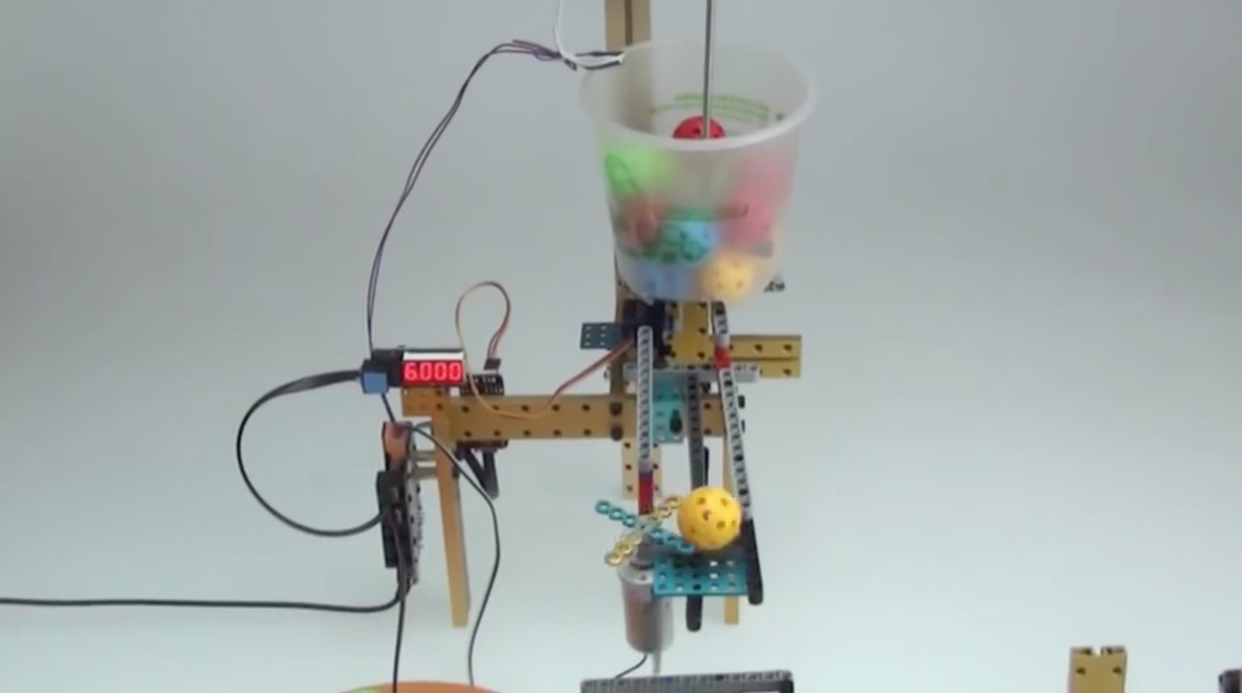
Since we don’t have an infrared sensor which could detect the object, we decided to build a smart structure which could give a response when the ball passes. As you can see in the video, we use a lever. The left side is a basket. When a ball is falling down, the limit switch is touched. It transmits a signal to a numerical display which shows the number of the balls. The electronic parts are based on Arduino.


RobotWeek_Badge_bur02

This week marks the official launch of Make: Volume 39 — Robotics, which drops on newsstands the 27th. Be sure to grab a copy at a retailer near you, or subscribe online right now and never miss another issue.

We are celebrating with five days of robot-related articles, pictures, videos, reviews and projects. Tune into this space for Robot Week!

Our next theme week will be wearable electronics. Send us your tips or contributions before it gets here by dropping a line to editor@makezine.com.


Project Steps

Build the Lever

The lever is very easy. Since all the Makeblock parts are compatible with Lego, you don’t need to worry about the connection. The distance between the holes is same. And there is a thread groove on the beam, very flexible.

The most important thing is, you need to find the right weight on the right side to balance the force while the ball is falling, as you can see in the video. There are two methods:

1st: Modify the distance between the basket and the weight. This is coarse tuning.

2nd: Fortunately, there are lots of holes on the Lego beam. You can put some screws in the holes to find the most appropriate weight.

Finally, install the limit switch on the right side of the lever. It should look like the 3rd picture.

Find a Container

In this case, I used a plastic cup which holds the balls at first. Cut a hole at the bottom of the cup so that the balls can pass through.

The hole should be the right size to allow just one ball to pass. The black points in the picture are two screws, which used to install the cup on the beam.

Build the Frame and Install the Electronic Modules #1

This the frame of the structure. It consists 3 parts: the groove, the bearing structure, and the electronic modules and motor.

Build the Frame and Install the Electronic Modules #2

As for the groove, you can build it with Lego parts. Fix one side on the frame, and place a motor on the other side. The motor is used to control the balls so the fall down to the lever one at a time. I used some hot-melt glue to fix two beams on the shaft of the motor. There is also a side-effect: the weight of the motor causes the groove to be slightly inclined. : )

Watch the video to see how it works.

After that, install the electronic modules and the cup on the beams. There are holes on the PCB so that you can just screw them on the beam.

Build the Servo System

In order to control the flow rate of the balls, I need an on-off mechanism at the bottom of the cup. In this case, I install a little servo.

Fix the servo on the beam with hot-melt glue.

Screw the servo and beam on the frame. You can use a 3×3 bracket to adjust the angle.

Build the Rabbling Mechanism

In order to prevent the balls from locking up in the cup, I need a rabbling mechanism to move the balls.

Extend the shaft of the motor with a coupling. Fix the beam on the side of the shaft.

Install the rabbling mechanism on the back of the structure.

Tips, in this case, I chose the motor whose rotation speed is 14 RPM, which has enough torque to move the balls when they lock up.

We have finished all the steps to build the structure. Next, let’s connect the cables and upload the program to make it move.

Connect Cables and Program

Me Baseboard is the controller in this case. And as for the connections, you might notice that there is a color tag on each modules of Makeblock. Please connect the them to the Baseboard’s PORT of whose color is same with the module’s.

MeServo servoDriver(PORT_3,DEV1);

MeDCMotor motor1(M1);

MeDCMotor motor2(M2);

MeLimitSwitch limitSwitch(PORT_6);

MeNumericDisplay disp(PORT_5);

After you finish the connection, please install Arduino IDE and install the library of Makeblock, you can follow the instruction here: http://wiki.makeblock.cc/index.php?title=Library_Download

Before uploading, click Tools->Board, choose Arduino Leonardo. And click Serial Port, choose COM XX(Not COM1 and COM2). Then, upload the program to Baseboard.

You can find the program here: http://forum.makeblock.cc/t/build-a-ball-counting-robot-by-makeblock-and-lego-complete-instruction-on-may-25/518

After that, plug in the power cable and open the switch to start the contraption. Adjust the structure and the program, especially the lever, to find the best balance for it.

If you have any questions, you will find me on Facebook, https://www.facebook.com/qy.xuma target=”blank”