I am descended from 5,000 generations of tool-using primates. Also, I went to college and stuff. I am a long-time contributor to MAKE magazine and makezine.com. My work has also appeared in ReadyMade, c't – Magazin für Computertechnik, and The Wall Street Journal.
I’m a dabbler, really, both at music and electronics. My fellow MAKE staffers put me to shame when it comes to circuit-savvy; when I started this kit I can comfortably say it had been at least four years since I’d soldered anything. But the POSC went together without a hitch.
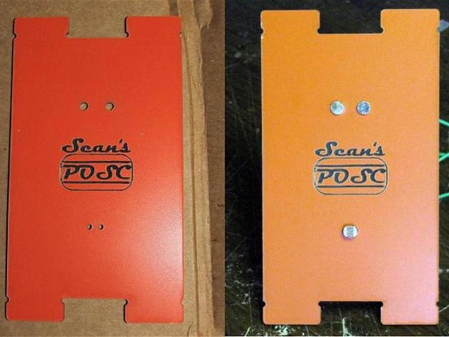
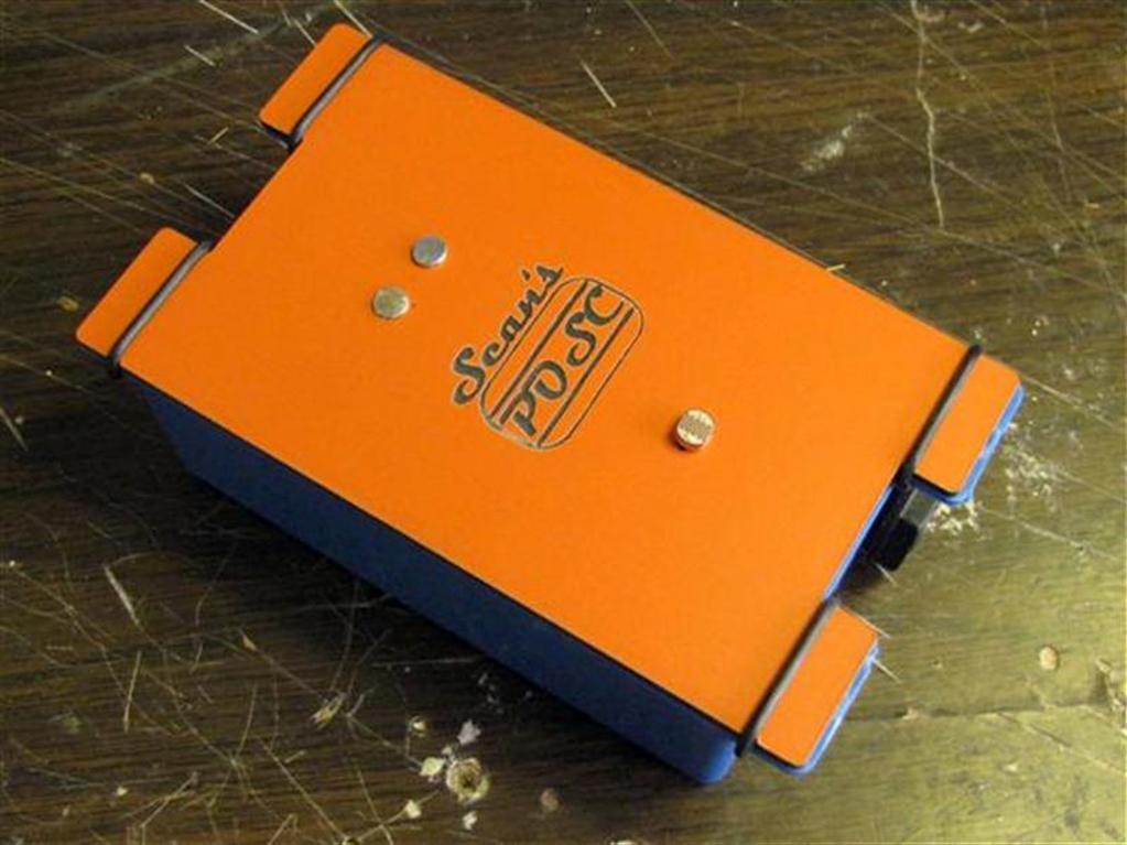
It was the enclosure that I really geeked out on, ordering a custom-cut and -etched cover in orange-coated 2-ply acrylic sign plastic from my pal Angus Hines. Angus is both the most competent and the least expensive CNC contractor I’ve ever had the pleasure to work with.
The plastic I used cost about $20, including shipping to Angus from the distributor, but the actual cutting and etching only cost $8 altogether. Angus still has a bunch of the material left, and anybody who wants to have a cover cut from it is welcome to do so.
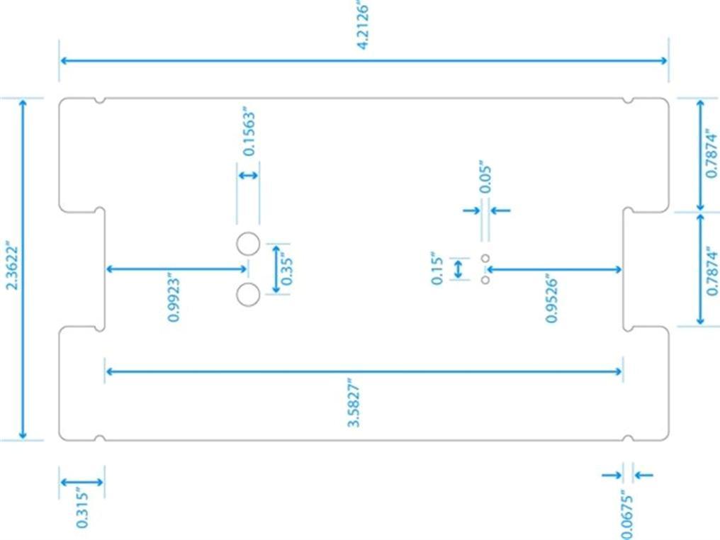
The panel has four openings to install three components: 1 hole each for the pair of zinc-plated finger contacts, and 2 holes for the leads of the photoresistor.
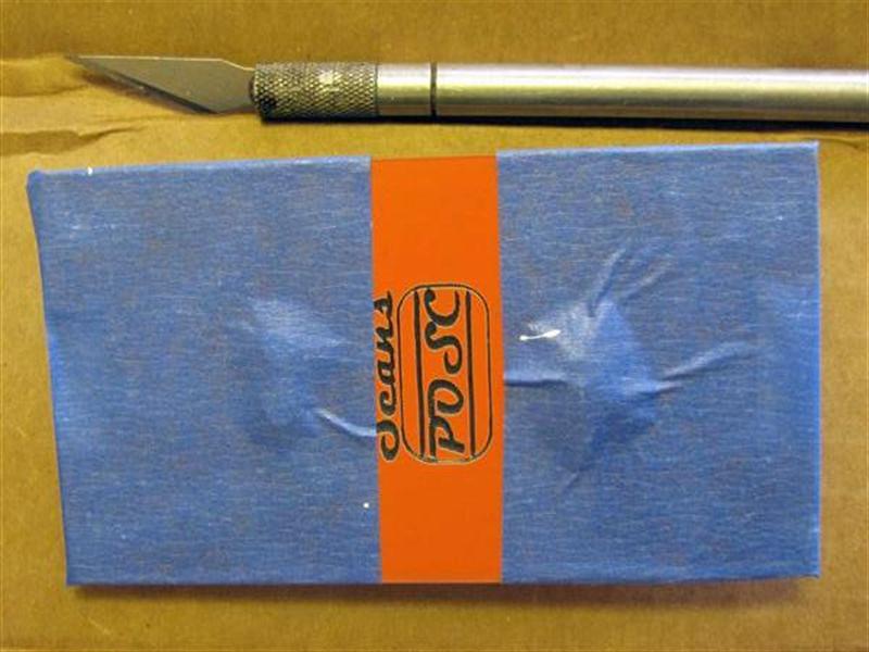
Seat all the components firmly against the front of the panel and hold them in place with blue painter’s tape. (NOTE: Stronger tapes may damage the finish on the plastic.)
Turn the panel face down and carefully solder pre-tinned lead wires to each contact and to each leg of the photoresistor. Be careful not to overheat the contacts, as conducted heat from your soldering iron may damage the plastic cover. Use a heat sink if you’re nervous about this.
Slip a piece of the included heat-shrink tubing over each lead wire and cinch them up tight against the rear face of the panel. Apply heat to shrink the tubing, but don’t overdo it. I used my soldering iron for this. If I were going to do it again I might try a cigarette lighter or candle flame.
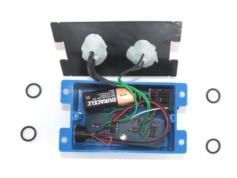
I had hoped that the heat-shrink tubing itself would be strong enough to secure the components against the cover, but alas, they were still wobbly when I got it in place. So I beefed it up with a couple of blobs of 2-part epoxy putty, which works great. Sugru might be a better way to go. I gently clamped the panel face-down against my bench when I installed the putty, and as it dried, to make sure the components remained firmly seated as the adhesive set up.
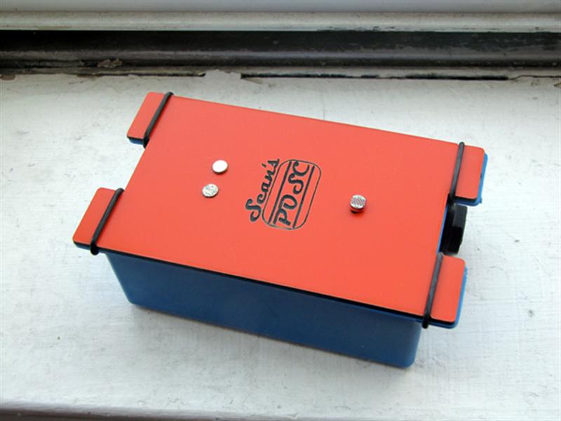
The enclosure itself is a blue PVC switch box that cost $0.80 at my local ACE Hardware outlet. The cover is held on with four black O-rings that slip around the tabs.
The switch box actually has two knock-out tabs that are about the right size for the power switch and the 1/4″ jack the POSC requires. I used a flat-head screwdriver to bend them over initially, and then just wiggled them back and forth to fatigue the plastic until they fell off. I cleaned up the bit of leftover flash around the edge with a hobby knife.
Neither knock-out opening was quite big enough, so I hogged each of them out a bit with a round file. This was not an exacting process: The plastic cuts quickly under the file, and I just kinda ground on it, poked, looked, and ground some more. Until it fit.
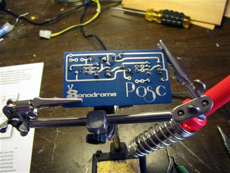
As pretty as Kat and Jim’s PCB is, it was too big to fit inside my switchbox with the 9-volt battery, switch, and jack in place. So I cut it down to size by scoring it with a hobby knife against a steel ruler, then breaking the board across the edge of the table. I was able to do this with all the components installed without breaking anything, but obviously it’d be better to do it before you attach anything to the PCB.
Bend the component legs using needle-nose pliers as needed, insert the legs through the right holes in the PCB (make sure you get the LED right way around, and the integrated circuits oriented correctly), then turn the PCB over and solder the legs in to the pads. Clip off the excess wire using nippers. Solder everything in place on the PCB side, then be sure you’ve got your switch, jack, and panel-mount components in place before soldering their leads on.
With the PCB trimmed down, everything just fits into the switch box as shown. I left about 4″ of slack on the panel-mount components, and this spools nicely into the compartment and pads the battery. When the cover is strapped on, nothing rattles at all.
Conclusion
When you first turn the POSC on, the LED will light for a fraction of a second. If you've got it hooked up to an amplifier, it'll also squawk for a bit. Playing it is as easy as licking your finger and tapping, rubbing, pressing, or smearing it across the two contacts. The amount of incident light on the photoresistor controls the frequency, so experiment with playing it under different lighting conditions. Jim and Kat have produced a bunch of software for digital post-processing of the POSC signal. For more info, see the Sonodrome website.
I am descended from 5,000 generations of tool-using primates. Also, I went to college and stuff. I am a long-time contributor to MAKE magazine and makezine.com. My work has also appeared in ReadyMade, c't – Magazin für Computertechnik, and The Wall Street Journal.
When you buy through links on our site, we may earn an affiliate commission.
Our websites use cookies to improve your browsing experience. Some of these are essential for the basic functionalities of our websites. In addition, we use third-party cookies to help us analyze and understand usage. These will be stored in your browser only with your consent and you have the option to opt-out. Your choice here will be recorded for all Make.co Websites.
Allow Non-Necessary Cookies
Escape to an island of imagination + innovation as Maker Faire Bay Area returns for its 15th iteration!
Buy Tickets today! SAVE 15% and lock-in your preferred date(s).