spin-the-birdie_opener

Bird Shot

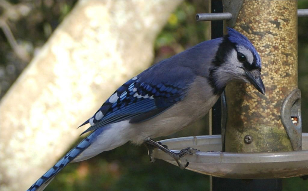
Birds make lousy subjects for digital photographs. They’re fearful, fidgety, and, well, flighty. But you can improve your odds of getting awesome avian photos by moving your camera closer to the birds — and yourself farther away. While you’re at it, why not get them to pose for you?

Since converting from film to digital photography more than ten years ago (I bought an Epson PhotoPC with a half-megapixel resolution for 500 in 1996), I’ve sought ways to take advantage of the “tons o’ shots to get a winner” phenomenon. Recently, I discovered that bird photography definitely falls into that category.

But digitally shooting birds taxes a camera’s resolution limit big-time: your 6 or 10MP digicam suddenly becomes another PhotoPC when you throw away valuable pixels by cropping. So, you have to get closer — but getting closer makes the birds more skittish and shy. It’s a digital catch-22.

We can have our cake and eat it too, though, thanks to a long shutter-release cable and a gadget that typically controls model vehicles: an R/C radio.

Feeder-Illo-1

To pose the birds, and to prolong camera battery life, I use an old R/C radio and its 2 servos: one actuates the camera’s power switch, and the other slowly turns the bird feeder!

To control my camera’s shutter release button, I use a long 3-conductor cable with 2 switches — the easiest, cheapest way to put your camera near the subject and shoot from a distance.

A shutter release button does 2 things: pressed halfway, it initiates metering and focusing; fully pressed, it fires the shutter. Some cameras have a jack for a shutter release cable, connected in parallel with the button; 2 switches at the other end are sequentially operable. The jack on my Pentax *ist DS camera accepts a standard 3/32″ (2.5mm) stereo plug, as do other DSLRs including the Canon EOS Digital Rebel, Samsung GX-1L, and Pentax K10D.

Project Steps

Make the shutter-release system

Construct the cable. You can buy a 3/32″ (2.5mm) stereo plug from RadioShack. But if you’re not into delicate soldering, spend a few bucks on an adapter cable (for example, yourcablestore part #HP 3M-2M 6) and cut off the ⅛” plug. Connect at least 50′ of cable to the 3/32″ plug. An old telephone cable with at least 3 conductors works great.

Mount switches on a switch block. The switch block is a noncritical block of wood that just holds your switches. Any pushbutton (momentary-on) switches will work, but 2 micro switches with different actuating pressures can be combined into a sequential switch.

Nail (yes, nail) them to the switch block. With 2 nails, mount the one with the greater actuating pressure below the one with the lesser actuating pressure, which pivots around its own single mounting nail (don’t pound it all the way down). Tap a small nail through the block from the back, to act as a stop for the pivoting switch. Wire as shown here.

Your cable is now testable! Plug the stereo plug into your camera’s shutter-release cable jack. Power up the camera. Press the first (or upper) switch, then press a little harder to actuate the second switch.

Build the camera power switch

Make the switch coupling. My camera’s main power switch rotates about 30° and has a small lever-like protrusion. If yours is configured like that, Dremel-shape a small section of plastic plumbing riser (pipe) to match the camera switch on one end and the servo horn (the part that moves) on the other. Then screw the horn and your homemade coupling together with the #4×½” wood screws.

Make the camera bracket. Mine is ugly and tortuously bent to hold the servo, receiver, and LED brackets. Make it from ⅛”×¾” aluminum extrusion. Be careful that the bracket doesn’t block the optical viewfinder or the LCD; you’ll need access to one of these for aiming and/or focusing the camera.

Make the servo and receiver brackets. Made from thin sheet metal, these brackets attach the servo and receiver to the camera bracket. Use the assembly screws for mounting the servo and the #6-32 screw to mount the receiver.

Build the camera power switch (cont'd)

Mount the camera bracket loosely to the camera (for testing) by trapping its lower end between the camera and your tripod with a longer ¼”-20 machine screw, replacing the tripod’s screw. Make sure the screw doesn’t bottom out in the camera’s tripod-mounting hole.

Add the servo and receiver. Ensure the switch end of your coupling just snugly engages the camera’s switch. Excessive pressure requires excessive torque (thus current) to turn the switch on and off.

Test the servo coupling. With the ¼”-20 screw loosened and the coupling disengaged from the switch, connect and turn everything on. Press the appropriate joystick to observe how many degrees and in which direction the coupling moves. You can reposition the horn on the servo, tweak the trimmer on the transmitter, and/or limit the amount and direction of joystick travel by gluing a couple of pieces of thin plastic, such as Formica, near the joystick.

MAKE AN INDICATOR FLAG: Tighten the ¼”-20 screw and add a small but visible-from-a-distance “Camera On” flag to the servo’s horn. Bend the music wire into an “L” shape and add colored tape or paper to the tip.

Spin the birdie

Make the feeder ratchet parts. The second R/C servo poses the birds by slowly ratcheting the feeder around. Make the ratchet parts by using the templates (the rest are pre-made, from the materials list).

RATCHET ASSEMBLY

  1. Feeder hanger Use a length of 3″×½” plywood to extend from your feeder support (pole, tree, etc.) to the feeder. Pre-drill appropriate holes in the other end to attach the hanger to your support.
  2. Click Use thin 1/64″ metal.
  3. Spring
  4. Pawl Use a paper clip.
  5. Pivot screw washers
  6. Ratchet spacers (3) made from ⅛” acrylic.

    Most any shape works as long as the hole is 1/16″ from the curved edge. These must clear the pawl.

  7. Ratchet support Use ½” plywood.
  8. Ratchet Make it from 1/16″ Formica using a band saw or a jigsaw mounted upside down; use a file to shape the teeth. The photo shows 14 teeth; it’s not critical as long as they’re fairly evenly spaced and the throw on your servo is adequate to advance the ratchet 1 full tooth.
  9. Ratchet pivot screw This pivot method using the 3″ machine screw is almost foolproof. If you use a wood screw, make sure its threads are at least 1½” long.
  10. Pivot screw nail
  11. Sheet metal screws #10×¾”
  12. #10 washers
  13. Feeder hooks Since feeders vary, you’ll customize these. Make them from 3/32″ brazing rod or a coat hanger. Bend an eye into one end of each hook for mounting to the ratchet. Use at least 2 hooks to smoothly transfer torque to the feeder.

Spin the birdie (cont'd)

Assemble the ratchet. Clamp the feeder hanger upside down in a vise. Using the second image and the third image as a guide, put together the ratchet assembly — except for the pawl and click.

Mount the servo to the feeder hanger with small wood blocks (servo configurations may vary).

Add the pawl and click. Connect a short, weak tension spring or rubber band between them to keep them engaged with the ratchet.

Connect and turn on the transmitter and receiver. Move the joystick, which actuates the feeder servo. Each pawl-pull should cause the click to engage an opposite-side tooth to prevent backward rotation. Each full cycle rotates the ratchet 24°–26°. You may have to adjust the action by slightly bending the pawl and/or click.

NOTE: To connect the ratchet assembly, extend the servo’s wires so that they’re longer than the distance from the feeder to the camera rig.

Make your camera feedback beeper (optional)

Only one challenge remains: a way to signal “Picture taken!” without having the flash go off in Birdie’s face.

On the back of my camera, there’s a small LED that indicates memory-card access. A photocell (photoresistor) mounted face to face with this LED can change resistance in a simple 555 circuit (see Make:, Volume 10, page 62, “The Biggest Little Chip”), creating or changing a tone in a speaker.

If your camera has this LED, make and mount another small bracket of thin sheet metal to bridge between the camera bracket and the LED. Drill a hole to fit the photocell, while holding it in good contact with the LED. Wrap black electrical tape around the assembly (don’t cover the face of the photocell!) and put a small O-ring around the photocell to shield it from extraneous light.

Build the beeper per the schematic shown, using prototype or perf board. Mount it near the R/C transmitter, then run 2 wires from the photocell, alongside the remote shutter-release cable, to the beeper.

Mount remote controls and wire it up

Since you’re running wires anyway, run another pair to power the receiver.

I mounted all the remote stuff in an old plastic power-tool case using hot-melt glue and wire pulled through holes in the case to hold everything in place. You can also glue foam blocks to the inside of the top.

Mount the meter/shutter switch block near the camera-on joystick, for one-hand operation. You’ll need the other hand to move the feeder-turning joystick.

Three more switches turn everything on: 1 in the transmitter, 1 for the receiver, and 1 for the feedback beeper. The 2 you add can be any SPST switches.

One 9V and two 6V (lantern-size) batteries power everything. To replace the (usually) 8 AA batteries in your transmitter, solder wires to the first (+) and last (-) battery terminals, run them out of the housing, and connect them to the lantern batteries, in series, with alligator clips. Wire the whole rig according to the diagram.

Get a bird's-eye view

Set the camera up and move away from it, as in the shutter-cable testing procedure.

Turn on the transmitter, receiver, and feedback beeper (if using). Move and hold the joystick to turn the camera on. (Watch the flag on the camera for confirmation.) While holding the joystick on, actuate the metering and shutter switches.

NOTE: If you’re using the camera feedback beeper, you’ll hear a beep (or a pitch change) from the speaker when you take a picture.

Now practice rotating the feeder by repeatedly moving its joystick s-l-o-w-l-y.

Get a bird's-eye view (cont'd)

Take another shot or two, then retrieve your memory card and download the picture(s) to your computer to check focus, exposure, composition, etc. (Unless you’re extremely lucky, you’ll probably just have beautiful shots of your bird feeder.)

Finally, reinsert a formatted memory card, get comfortably away from the feeder, and hold the plastic case in your lap. Don’t turn on the camera until a bird lands on the feeder.

Using both joysticks and the meter/shutter switches, take lots of pictures while you slowly rotate the feeder to the best camera angle. You may also turn the feeder between bird visits; they may prefer certain feeding positions to others.

Get a bird's-eye view (cont'd)

Do the birds like to be rotated? Eventually, most of them adapt. Some are more skittish than others; some actually seem to enjoy it. The female red-wing blackbirds stop eating and look up at the sky. Blue jays bolt. And cardinals just smile.