This guide will walk you through the assembly of the electronics for the Make Vector Weapon Kit. When you’re done with the build, it should sound like this and look like this:
Assembled

This circuit was designed by Chris Lody, a fabulous Maker who’s invented an impressive array of musical circuits. Chris’ original design for the RayGun Vector Weapon appears in Volume 35 of MAKE Magazine, as a stripboard DIY project and with an optional sci-fi, laser-cut enclosure.

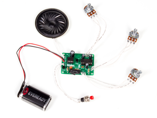
Unlike the stripboard version found in the magazine, the Maker Shed kit is hassle-free, with all parts included (except the 9V battery) and each component clearly labeled on the board. This is a great through-hole kit for an aspiring soldering pro, and makes absolutely awesome sounds when it’s assembled.

If you bought the complete kit, you’ll have to assemble the enclosure when you’re done with the electronics.

Project Steps

Gather all the parts

Refer to the parts list at the top right of this page to make sure you have everything. If you’re missing a part, please let us know by emailing help@makershed.com.

Install and solder the first IC Socket

Grab the PCB and the larger of the two IC Sockets (14 pin). Insert it into the top side of the PCB, ensuring that the small “dimple” is facing left, the same side as the small circle on the board.

You can also solder the ICs directly into the PCB, but the sockets allow you to replace the IC in case of part failure.

As you can see in the third photo of this step, I bent two of the socket’s leads in order to hold it in the PCB while I soldered. You can also just set everything upside down on your bench for soldering this step.

Install the smaller IC Socket and two caps

Repeat the same installation and soldering process for the smaller, 8-pin IC Socket.

Next, we’re going to solder in the four electrolytic capacitors (all four are black and cylindrical). It really doesn’t matter what order you go in, but I started with the largest one, 220 uF. Note the polarity here — the negative side of the cap is noted by the white stripe. Make sure you install it correctly on the board!

Repeat this process for the next cap, the smaller 4.7 uF one on the top right of the board. Again, note the polarity — the white stripe corresponds to the negative side.

The rest of the electrolytic caps and the transistors

Install the last two electrolytic caps (100 and 2.2 uF) in the same manner as the last two, again noting polarity.

Next, the two 2N3904 transistors. You’ll have to bend the middle leg back a bit before squeezing these into the PCB. Make sure they’re installed in the orientation that’s drawn onto the PCB, as seen in the third photo here.

Resistors and the ceramic caps

There are only three resistors in this assembly: (1) 1kΩ, which resides on the bottom left side of the board, and (2) 470Ω resistors. Polarity doesn’t matter here, so you can solder them in whatever orientation you want to.

Now for the final two capacitors — the small, orange ceramic ones. The one labeled “104” has a value of 100 nF (or 0.1 uF). Like resistors, polarity doesn’t matter with capacitors of this size.

Insert and solder the slightly smaller ceramic cap, the 47 nF (or 0.047 uF) one. It has “473” printed on the front.

Install the LED and LDR

This is the most important step of the whole assembly. The LED/LDR combo is the driving force behind the kit, creating the oscillations by sending a pulse through the LED right to the LDR.

First, insert the LED (note the polarity — the longer leg, the anode, is positive) and bend it 90 degrees. Next, insert the LDR (polarity doesn’t matter) and do the same. Ideally, the components are touching each other.

Next, while holding both components together, gently lift them out of the PCB so you can fasten them together. You’ll need to use electric tape or heatshrink here, and please, wrap it up more than I did in the second photo (I went back later and added more tape). We want this little assembly as contained as possible, so don’t scrimp on the tape/heatshrink!

When you’re satisfied that the assembly is properly taped, heatshrunk, or enclosed in some other way, insert both components back into the board and solder away.

Install the 9V battery clip and section the wire

Now it’s time to solder the 9V battery clip in place. The red wire indicates positive, so make sure it’s in the hole with the (+).

Next, grab that long section of wire, which should be ~48″, and cut it into sections. Since we have 13 solder-joints left (3 for each potentiometer and 2 each for the speaker and trigger), cut them as follows:

(11) 4″ sections, for the potentiometers and trigger & (2) 2″ sections, for the speaker.

Don’t forget to strip both sides of each section of wire. Roughly 1/2″ on each end should do it.

Prepare the Potentiometers

Find your three potentiometers. Two should be 1 MΩ and one should be 100 kΩ. As you can see in the first photo, I bent the three connection points 90 degrees to make them easier to solder to, but that’s optional.

Now you can start soldering! I find it easiest to bend the stripped section of the wire around each potentiometer terminal before soldering — no helping hands needed! If the tip of your iron is small enough, you can rest it in the terminal while soldering.

Repeat this step for all three potentiometers.

Prepare the Speaker

I’d recommend adding a bit of solder to both joints on the speaker. Set it flat on the ground or use a pair of helping hands to keep it still.

Tin one end of your two pieces of wire as well. This is where the helping hands really come in handy!

Now hold each wire against the joint on the speaker and heat both up with your iron to complete the assembly.

Prepare the trigger and complete the assembly!

Last, solder the last two wires to the trigger. They should fit nicely into the holes of the trigger pins, so this shouldn’t be too difficult. Solder the other ends to the PCB.

Don’t forget to install the two ICs and a 9V battery. And that’s it, you’re done! Enjoy using your Vector Weapon, and please share a photo with us if you end up storing it in a nice enclosure.

When using your Vector Weapon, it is possible to orient all three knobs into a position where you won’t get any output, and that’s ok! Experimentation is required :)

Did you buy the complete kit from the Maker Shed? Head over to the next project to build your enclosure.