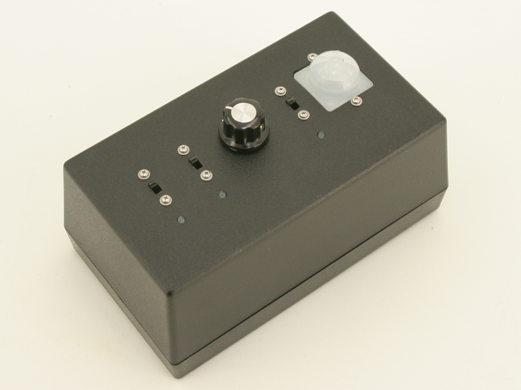
Build your own motion-sensitive camera trap for Nikon cameras with the kit available from the Maker Shed here.

This kit is based on Tom Igoe’s Nikon camera trap in Make 22: How to Make a Motion-Sensitive Camera Trap.

Project Steps

Drilling and filing holes for parts

Download the camera trap templates in this guide.

Center punch all the center marks on the drill holes.

Arduino holes have different hole spacing depending on their version.

Drill all the holes according to the template.

Make sure to clamp down the box when drilling the 5/16″ hole for the potentiometer.

Use a pair of wire snips to cut the between all the holes for the PIR sensor to form the square hole.

Push out the plastic and file the edges flat to the line on the template.

File the rectangular holes for the switches.

Mount parts onto project box

Mount the switches onto the project box by sliding each screw through a washer, the box, and switch. Then tighten the screw with nuts.

Mount the potentiometer onto the box with a washer (that came with it) on both side of the box. If the potentiometer doesn’t fit, enlarge the hole for the flange of the pot by running a 7/64″ or 1/8″ drill through the hole. Screw on the nut to secure the pot in place.

Place the LEDs onto their holes with the positive (longer) leads facing towards the wall of the box. Then hot glue them in place.

Leave the PIR sensor alone for now.

Cut out the headers

Cut all the female headers out by using wire snips. Cut directly over a socket/pin. A socket will be sacrificed to cut out the header.

Snap all the male headers to the sizes shown on the wiring diagram.

Solder everything together according to the wiring diagram.

Download the wiring diagram in this guide.

Tin all the header pins and all the ends of the wire that need to be soldered to the pins to form good connections. Make sure to solder only onto the shorter pins of the male headers to allow the longer pins to go into the Arduino.

Hot glue the solder joints to insulate them. You may also hot glue the resistors to reinforce the the solder joints on them.

Finishing touches

Screw on the PIR sensor with the longer #1-64 screws.

Insert the IR LED into its hole and hot glue it in place.

Screw on the standoffs with the #4-40 screws and then place the Arduino on top of standoffs and screw it down too.

Place the knob onto the potentiometer’s shaft. Use the slotted screwdriver to tighten the Knob’s setscrew onto the shaft.

Plug in all the pins according to the wiring diagram. Make sure the power switch is to the left (off position) when looking at the front of the box.

You’re finished building. Plug in the USB cable and get ready to program your Arduino!

Programing the Arduino

Download the Arduino IDE, available at http://www.arduino.cc/en/Main/Software

Install the Arduino IDE. Visit http://arduino.cc/en/Guide/HomePage for instructions.

Download the camera trap code and Nikon Remote library from https://makezine.com/22/cameratrap/

The folder named NikonRemote is the library to blink the IR LED in the correct pattern to trigger the camera. Move the whole folder to the libraries folder in your Arduino folder

Plug in your Arduino to your computer.

Run the Arduino IDE and open camera_trap_code.pde

Under Tools, goto Board, then select your Arduino model.

Under Tools again, go to Serial Port and select the port you plugged your Arduino into.

Click the play button to verify that the program compiles with no errors.

Click the upload button to upload the program onto your Arduino.

Remove the USB cable to disconnect the Arduino from your computer.

Using your Camera Trap

Flip the power switch to the right to turn on the Arduino.

Flip the intervalometer switch (below the potentiometer) to the right to turn on the intervalometer mode. This mode takes a picture every set interval determined by the position of the potentiometer. Turn the knob clockwise to speed it up.

Flip the PIR sensor switch to the right to turn it on. In this sensor mode, the PIR sensor will trigger when it detects a change in IR level. After it triggers, there will be a delay for it to reset to be ready again.