BOM

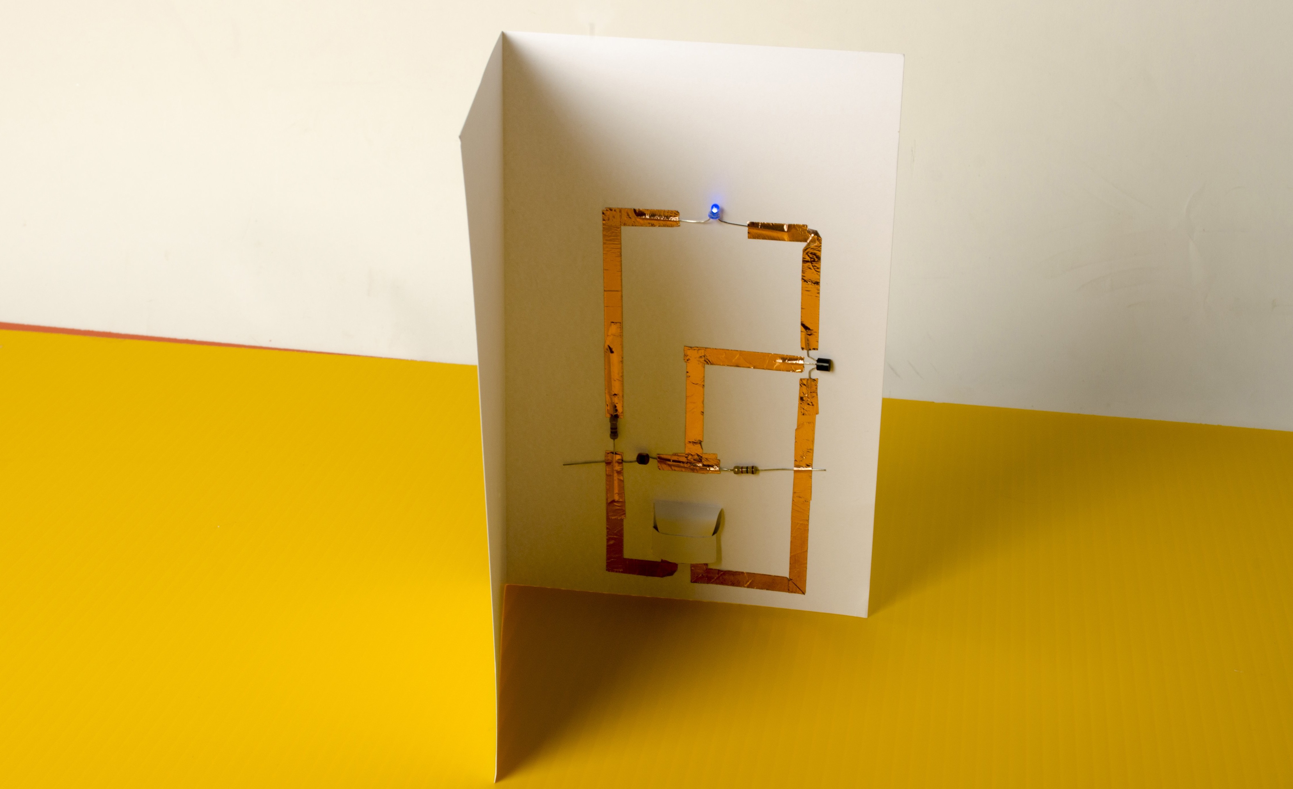
Electronics greeting cards are a great, approachable project for beginners to assemble in under an hour.

You won’t need to plug in a soldering iron, since these cards are wired using a special conductive foil tape. Not only is this tape conductive, it’s super sticky and it remains conductive even through the adhesive. While making this card, you’ll gain familiarity with common electronic components and end up with a nice gift for a friend.

Project Steps

Download and cut the battery diaper

Get started by printing out the paper battery holder. The first file is for those who simply want to cut the patterns out by hand. The second file is for those that want to laser cut the battery holders out.

Check out the work of Jie Qi, who inspired the design of the battery holder for this project.

YouTube player

Note: If you don’t want to build the battery diaper — as it’s affectionately called around the office — you can simply tape the two coin cell batteries together, stick conductive tape on the top of the battery stack and on the bottom. Make sure the conductive tape does not touch itself, otherwise you’ll short out the batteries and the project will not work.

Assemble the battery holder

Create an “L” shape with the coper tape as shown, leaving at least an inch of tape hanging off the edge. This will be the battery’s positive lead.

Flip the battery holder over, and orient the strip of paper beside the positive lead away from you. Starting at the edge of the strip, stick the copper tape down along its length and leave the excess dangling off the battery holder (as shown).

Note: The CR2032 coin cell battery is commonly used in small, compact projects. These batteries deliver 3-volts — abbreviated as 3V — and offer 250 mAh — miliamp hours.

Assemble the battery holder (cont'd)

Flip the battery holder over again, and fold the strip that was just taped along the dotted line so that the copper tape is on the outside, then fold again along the next dotted line. This tab will become the negative contact for the battery.

Fold the strip one last time along the third dotted line so that it overlaps the rest of the battery holder.

Fold the remaining tab over the newly created battery contact, and use double-stick tape to fasten the end of the tab on the opposite side of the battery holder. This creates the envelope for our batteries to sit in.

The rest of the battery holder acts as a flap to hold the batteries in after they’re inserted.

Install the battery pack

Add double-sided tape to the back of the battery pack and place it in the bottom, middle of the card.

Note: Adhesive backed, copper foil is essentially a wire in a different form factor. This particular type of foil uses a special adhesive that does not reduce conductivity.

Place the LDR

A light dependent resistor (LDR) is a special type of resistor that changes its resistance based on light levels. The LDR used in this project increases its resistance in the dark, and decreases in the light.

Place the LDR with one lead connecting to the copper tape from the left side of the battery. Secure the other lead of the LDR down with another piece of copper tape just above the battery.

Wiring the 470 Resistor

The 470 ohm resistor here acts as a current limiting resistor for our LED.

Use copper tape to connect one lead of the resistor to the tape from the left side of the battery, and connect the other lead to another piece of tape above it.

Wiring the 1k Resistor

The 1k resistor will act as one half of a voltage divider with the LDR.

Connect one lead of the resistor to the tape above the battery, and the other to the tape coming from the right side of the battery.

Note: The color bands on a resistor’s body indicate their resistance. For example, a 1k resistor has the colors brown, black, red. The gold band on the body indicates the tolerance of the resistance in ±

Taping the Transistor

The transistor (PN2222A) in our circuit acts as a switch controlled by the voltage divider to turn the LED on and off.

Bend the leads of the transistor as shown in the photo above, and set it on the card above the right lead of the 1k resistor in the orientation shown.

Connect the bottom lead of the transistor to the tape from the right side of the battery, the middle lead to the tape between the LDR and 1k resistor, and the top lead to a piece of tape above the transistor.

Adding the LED

Attach the longer lead of the LED to the 470 ohm resistor lead on the left, and the shorter lead to the top lead of the transistor.

How it works

Cover the LDR with your hand, or close the card, and the LED should turn off.

The LDR and 1k resistor form a voltage divider, which splits the voltage of the battery across the two resistors in proportion to their resistances. When the LDR is dark, its resistance is high, so there is only low base bias voltage on the transistor. As a result, current does not flow through the transistor, and the LED will not light up.

When the light level on the LDR increases, the resistance of the LDR decreases, and the base bias voltage on the transistor rises. Once it reaches a certain level, current is allowed to flow, and the LED lights up.