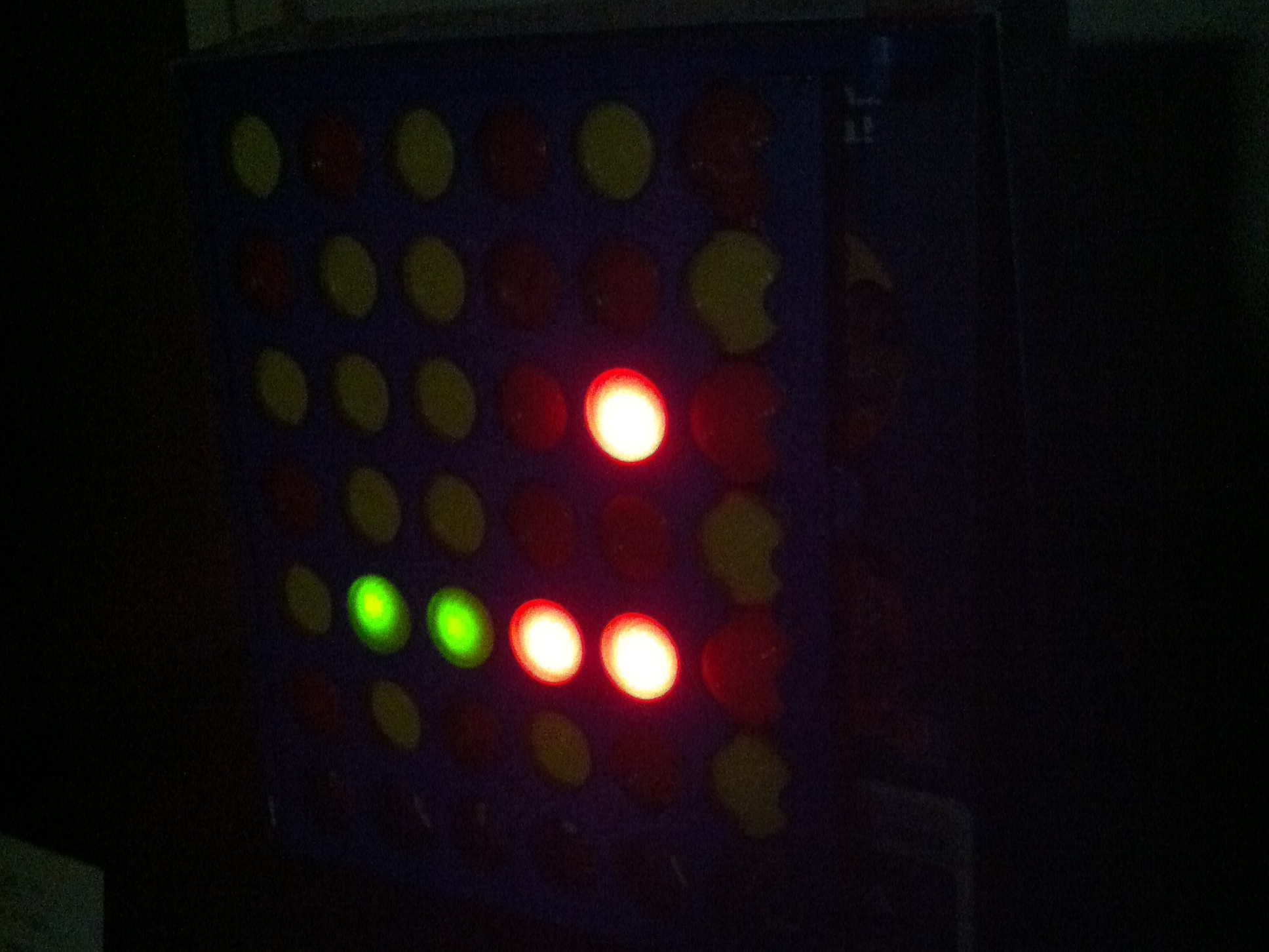
Remember that old Connect 4 game sitting in your basement/closet/chest/Batcave? You’ve always wanted to upcycle that into a functioning binary clock utilizing the awesome powers of an Arduino, haven’t you? Of course you have! Well, you’re in the right place!

This is a great weekend project that will provide you with a binary clock that is sleek and nostalgic all at once. We focused on recycling every part of the Connect 4 game to exemplify our "green" standards, and be as creative as possible. The Connect 4 works superbly in displaying a binary clock because it has perfectly rounded holes to showcase the LED-based binary numbering system.

You don’t need many supplies to make this binary clock, and it’s a great way to utilize an old Connect 4 game if you’ve lost some of the pieces, or simply want to show off your mad creative skills. And don’t worry about the coding – which we struggled against in an epic battle between sanity and madness – we already have it laid out for you! There’s not much of a time commitment and a fun result is waiting for you, so let’s get started!

Authors:

Mike Esposito

Luke Foley

Deniz Pamukcu

Many thanks to:

Marc de Vinck

– Michael Lehman

TE Class of ’13

[This project was originally published in December, 2012]

Project Steps

You know you want to make a binary clock from your old Connect 4 game set, right? Well, this is the best place to get started!

Take the Connect 4 game board and square it up to the box cover.

Mark the centers of the 13 holes in the middle of the board.

You will next want to find a drill bit that most closely matches the threaded part of the LED holder. Keep in mind that you can always re-drill a hole with a larger bit so err on the side of caution.

Now get that drill! Insert the bit and drill holes in the marks you previously made on the Connect 4 box. Make sure you go completely through the box so that the LED holders will have no problem fitting flush to the box.

Remove the rubber stopper from each LED holder, and slide the LED leads all the way through the rubber stopper.

Push the LED holders through the holes you just drilled, and tighten them down with your wire strippers, pliers or a small wrench.

Now you can take the LED attached to the rubber stopper and place it in the holder. Make sure to push the rubber stopper into the LED holder until it can’t go any farther.

Make sure you test each LED with a 3.5V battery!

Push the thirteen 220Ω resistors into the breadboard as shown.

Remove the breadboard’s adhesive cover and place the breadboard inside the box. Make sure it is on the bottom of the box, and it sticks! If there’s no adhesive backing on the breadboard, just use duct tape.

Measure out a positive and negative wire length from each resistor to each LED. Cut and strip the respective lengths of wire, and twist the positive and negative wires around the LED leads. (The positive lead is longer on LEDs!)

Make sure you ground each negative lead to the grounding rail!

Facing the back of the box, make sure the leftmost resistor is connected to the bottom-most LED in the left-most column. Then move vertically up the column before moving to the next column on the right.

Soldering is optional – you could use electrical tape as well.

Solder each positive and negative lead to the LEDs to create a stronger joint.

Use the wire snips to cut off any excess lengths of wire. Remember, you want to make the connection as clean as possible.

Since the Connect 4 board has some protrusions, trace out the sections that doesn’t allow the board to lie flat against the box.

Cut out the trace using the box cutter, and your Connect 4 board should lie flush against the surface!

Get the code!

The code can be found on the Instructables link here.

Cut fourteen 6″ strips of wire, and hook up pins #1 to #13 on the Arduino to the resistors on the breadboard – again, from left to right facing the back of the box.

Use the last wire to hook the ground pin (GND) on the Arduino to the grounding rail on the breadboard.

Take the 3/8″ drill bit and drill a hole through the side of the OTHER box top (the one you didn’t drill holes through in the previous steps).

Push the box tops roughly half-way together, and feed the power cord through the hole you just drilled, and plug in the Arduino.

Push the two box tops together to hide any wiring, and glue them in place with your superglue.

Take the game’s playing pieces and push them into the board from the bottom (the top will most likely be inaccessible at this point).

Try to keep everything looking nice and pretty! We went with yellow chips covering the green LEDs, and red chips covering the red LEDs. Try other arrangements to see what works best!

That’s all, folks! Have fun with your sleek and modern binary clock. Now go buy another Connect 4 game, and see what other cool projects you can do!

Check out my other projects on Instructables,

and my blog at DoG Studios.