YouTube player

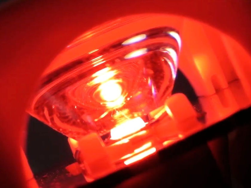
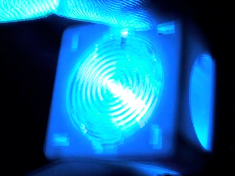
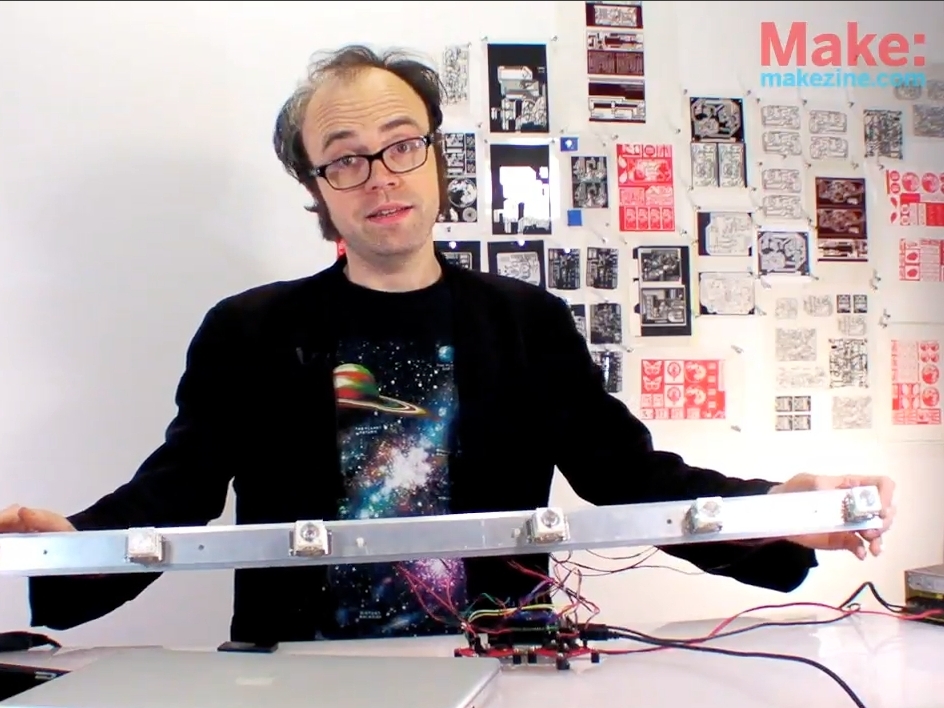
I’ve had color organs on the brain since the last installment of the circuit skills series, so I decided try my hand at a new incarnation of the basic 3-channel sound-to-light machine using high-power LEDs.

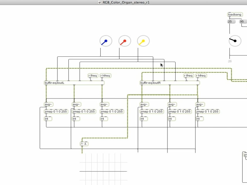
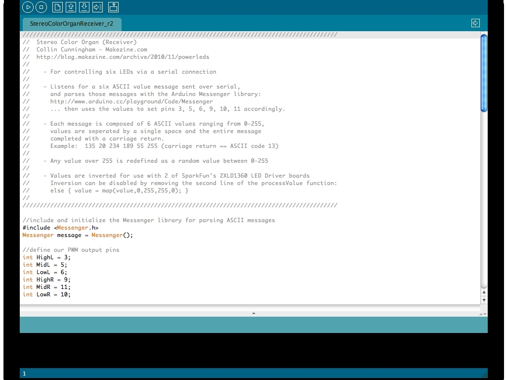
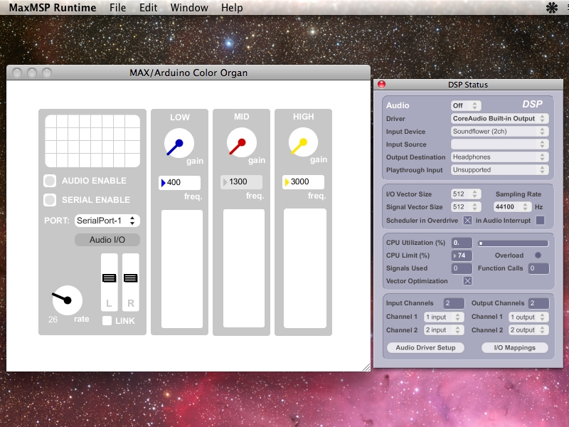
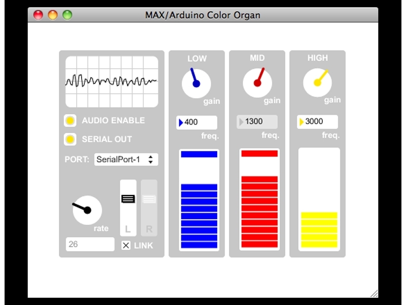
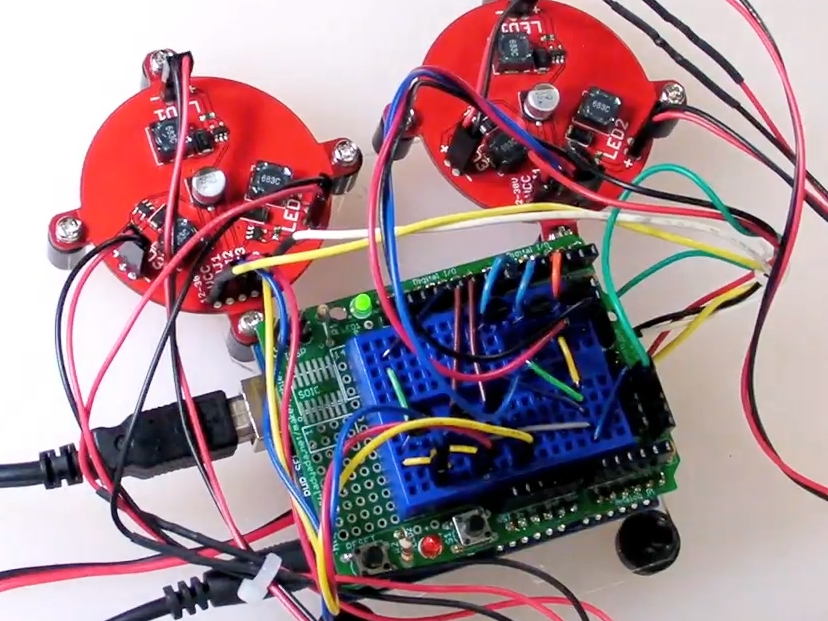
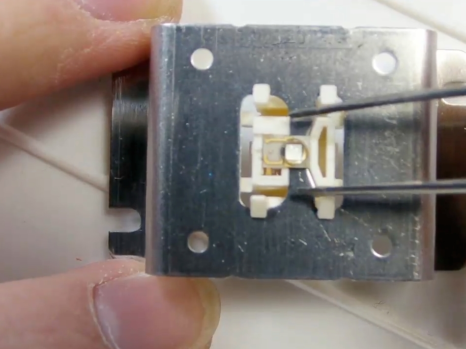
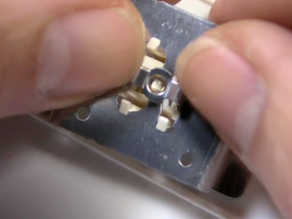
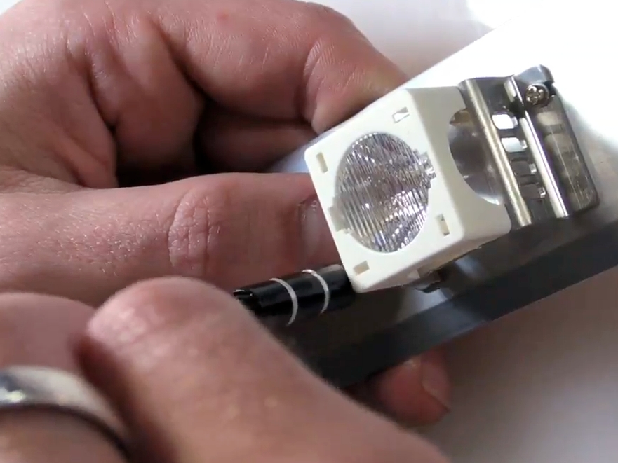
This time, I took advantage of the fact that I play all of my music from a computer, and created a ‘patch’ in MaxMSP to calculate high, mid, & low values of the outgoing audio stream. Max then sends these values out to an Arduino via serial connection over USB. The Arduino then uses these values to set the individual PWM outputs of 6 different pins. I wired each of these output pins to a couple of Rebel Tri-Driver boards which powered my Luxeon Rebel based display. Alternatively, a much more affordable low-power display could be created by simply connecting each of those PWM outputs to a 5mm LED and resistor wired in series.

Project Steps

Download Patch and Code

First download the Max patch & Arduino code for this project here.

To run the patch, you’ll need to download & install the free cross-platform Max Runtime (link @ top righthand side of the page).

The Max Runtime will also require some additional software in order to listen to your computer’s outgoing audio. I used Soundflower to do this on my Mac, Windows & Linux users should check out Jack (haven’t used it myself, but I believe it should work for this).

Upload to your Arduino

Upload “StereoColorOrganReceiver_r2.pde” to your Arduino. Leave the Arduino connected to your computer via USB but quit/close the Arduino IDE. You may need to download the Messenger library here http://www.arduino.cc/playground/Code/Me…

Set Arduino to recieve audio

In OS X, set “Soundflower(2 ch)” to “Built in Output” and in the “Audio Setup” app/utility, then set Soundflower(2 ch) as the audio input device.

Open “Max-Serial_Color Organ.mxf” file with the “MaxMSP Runtime” app. Click on the “Audio I/O” button and in the DSP Status window that opens, set input device to “Soundflower(2 ch)”.

Start some audio playing in the application of your choice (iTunes, WinAmp, etc.) and click the button next to “AUDIO ENABLE” (you should see a waveform animate the oscilloscope viewer now)

Choose the address of your Arduino from the pulldown menu to the right of “PORT:” Click the button next to “SERIAL ENABLE” Your Arduino should now be receiving values and setting the PWM outputs accordingly.

Connect LEDs

The Arduino sketch maps the values in the following way:

High Left = pin 3

Mid Left = pin 5

Low Left = pin 6

High Right = pin 9

Mid Right = pin 11

Connect each of these pins to an LED with an appropriately sized resistor to limit the current. (online calculators can be handy)

Alternatively high power LEDs could be used in conjunction with a separate power supply and/or driver board.

Close ups

Affix the LEDs to mounts

LEDs in action

Test out your LEDs

Drilling bar for LEDs installation

Drill holes and install your LEDs

Final product

Have fun!