There are a lot of electrical devices that only have two settings: ON and OFF. For a many of these, it would be helpful if you could adjust the output with an external circuit.

So in this project, I am going to show you how to make an adjustable power outlet. This circuit acts as an external dimmer and can be used to adjust the power on a variety of appliances such as Lamps, heaters, soldering irons, and hot glue guns.

Safety Note: 
The circuit used in this project is designed for simple resistive loads such as heating elements and lights. It is not suitable for inductive loads such as motors or fans. These generally require a different kind of control circuit. Also it should not be used with devices that use AC power adapters or devices that have their own built-in control circuits. These may not function properly when connected to a dimmer.

Project Steps

Materials and Tools

Materials:

3 Prong Power Cord

Insulated Plastic Housing

Light Dimmer Circuit

15A Outlet

Insulated Twist-On Connectors

Black and White Large Gauge Wire (optional)

Tools:

Wire Strippers

Screw Driver

Knife or Rotary Cutting Tool

Drill

Background: How a Dimmer Circuit Works

The AC electricity from an outlet is basically a sine wave. Most modern dimming circuits work by chopping off part of the sine wave. Above is a simple schematic of this kind of dimmer circuit. These circuits use a semiconductor called a TRIAC. A TRIAC conducts electricity only after the voltage at the gate pin has reached a certain threshold. It is often combined with a DIAC to increase this threshold voltage. The DIAC/TRIAC is connected to a resistor and a capacitor. The resistor sets how quickly the capacitor reaches the threshold voltage. By adjusting the resistor, you determine how much of the sine wave gets chopped off.

At the first part of each cycle, the TRIAC is off. The capacitor begins to charge through the variable resistor. When the voltage of the capacitor is high enough the DIAC/TRIAC is activated and it conducts electricity to the lamp. This process happens at the first of both the positive and negative parts of the sine wave.

Purchase or Built a Dimmer Circuit

You can purchase a lamp dimmer at most hardware stores for a few dollars. There are a variety of types available. The most common type is a dimmer light switch. This is typically mounted to a wall in place of a standard light switch.

The type that I am using in this project is a “500 Watt Torchier Lamp Dimmer.” It is normally used to retrofit a regular lamp to add the dimming feature.

If you would rather build a dimming circuit from scratch, you can find a number of designs online. Here is one example:

Cut Holes in the Plastic Housing for Each Component

Open up your plastic housing and decide on the best locations for the dimmer circuit and the outlet. On mine, I decided to mount the outlet to the top surface and dimmer circuit to the front side. This left a convenient place to put the power cord on the left end.

First, you need to mark an outline of the front faces of the outlet. You can do this by holding the outlet upside down on top of the housing and tracing it. You could also use an outlet cover plate to mark the appropriate outlines. Then using a sharp knife or a rotary cutting tool, cut out the two outlines. Then drill a hole between them for the mounting screw. After cutting these holes, mount the outlet in place and secure it with the screw.

Once the outlet is in place, you need to mount the dimmer. Hold it up to the side of the housing and mark where the knob will be located. At this point, drill a hole in the side of the housing that is just bigger than the threads on the dimmer. Then insert the knob of the dimmer and secure it in place with the washer and nut.

On the left side, I drilled a hole that was just bigger than the power cord. Then I inserted the power cord through the hole.

Connect the Dimmer to the Power Cord and Outlet

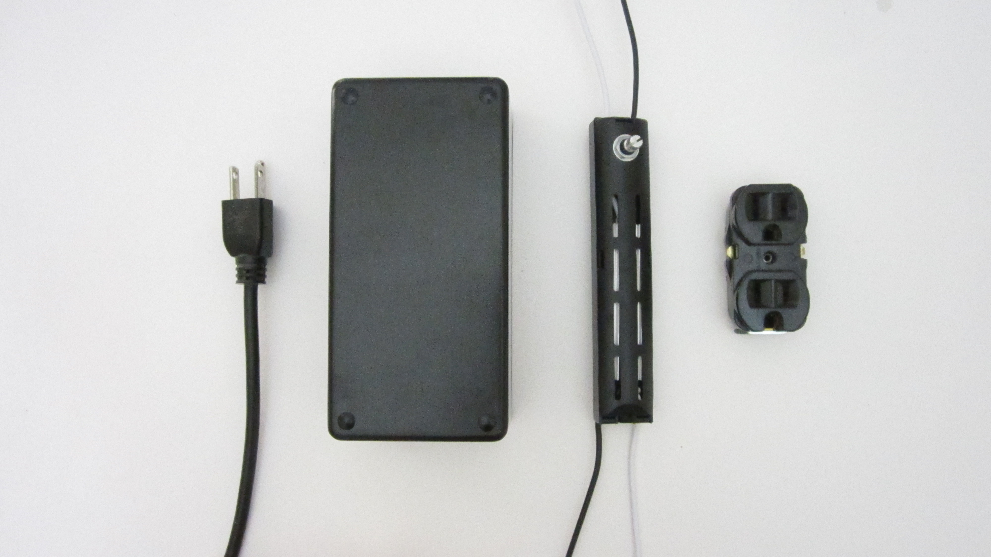
Before you connect anything, it is important to first identify all the wires. The dimmer and the outlet need to be connected in a certain configuration. The color coding system for electrical wires varies from country to country. In the United States, white wires are “neutral”, black wires are “hot” and green/bare wires are “ground.”

If the wires are not color coded, then it may still be possible to identify them from the prongs on the plug or the texture of the insulation. “Neutral” wires are typically connected to the wide prong on the plug and have ridges on the side of the insulation. “Hot” wires are typically connected to the narrow prong on the plug and have insulation with a sooth side.

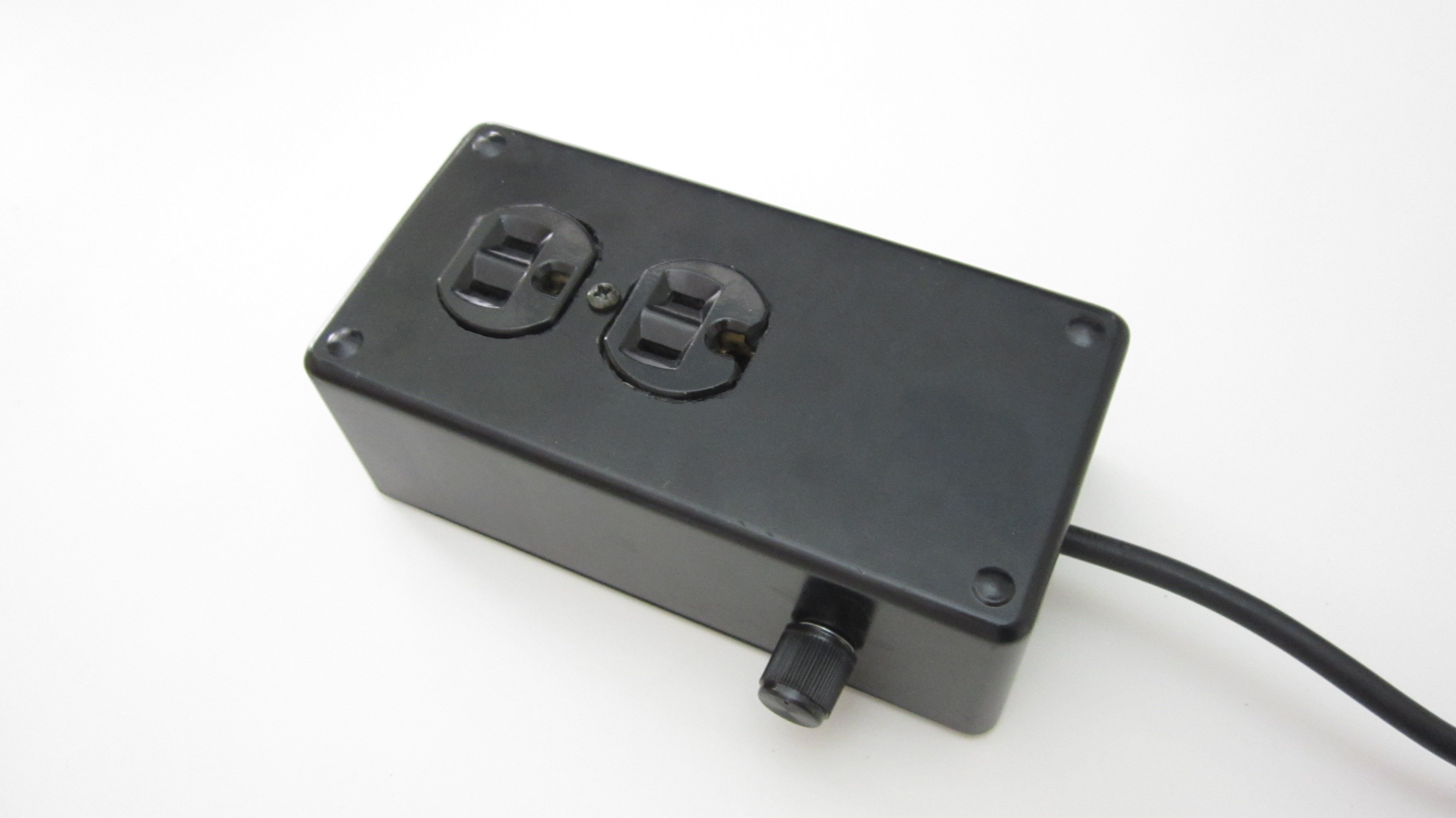
After identifying the wires, you are ready to connect all the components. Insert the power cord through the hole in the side of the housing. If you want to make the power cord a little more secure, you can apply glue or a zip tie around it at the wall of the housing. This will help to prevent it from being pulled out and breaking the connections.

Connect the “ground” wire (green or bare wire) from the power cord to the nut on the end of the outlet. Then connect the white wire to the slot on the outlet that is labeled for white wires. Connect the black wire from the power cord to the black input wire on the dimmer. Then connect the black output wire from the dimmer to the slot on the outlet that is labeled for black wires.

If the wires need to be solid in order to be inserted into the outlet, then you may need to add a few small pieces of solid core wires. Connect the solid core wire to the outlet. Then connect them to the corresponding wires with insulated twist-on connectors. After making all the connections, close up the housing. Your adjustable power outlet is complete.

Use Your Adjustable Power Outlet

There are a lot of potential applications for an adjustable power outlet.

The simplest application is as an external dimmer for lamps. This can let you adjust the brightness of any incandescent light (and some LED lights). This can make interesting effects with novelty lamps such as lava lamps.

This outlet can adjust the output of any appliance that uses a simple resistive heating element. Examples of this include: soldering irons, hot glue guns, hot wire foam cutters, crock pots, counter top grills and some coffee pots.

As noted in step one, this outlet is not designed to work with inductive loads such as motors or devices that use AC power adapters or devices that have their own built-in control circuits.