Braverman-1H2A8822rgb

This article first appeared in Make: Volume 41.

In the past few years we’ve seen huge advancements in desktop 3D printing. At home, at your local hackerspace, or even your community library, you can design and print an endless variety of items and customize them to your individual needs.

Where desktop 3D printers fall down, though, is in creating large numbers of the same thing. 3D printers tend to be slow and error prone. One way to quickly manufacture your parts is traditional casting: making molds and pouring resin. But resin can be expensive, and this technique only makes solid models.

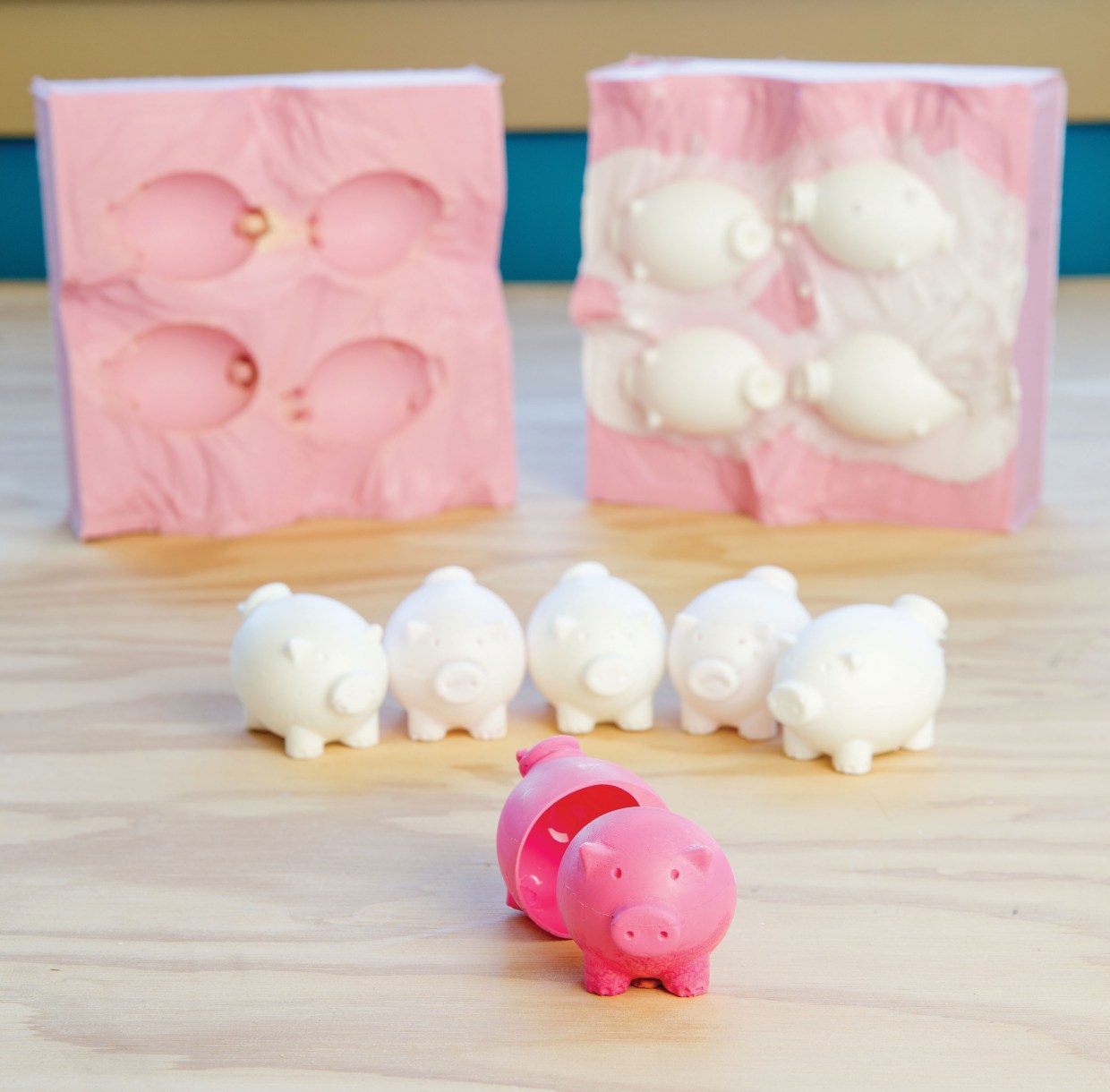
That’s where rotocasting saves the day. By slowly spinning your mold, you can produce hollow, lightweight parts using just a quarter of the resin. In this project you’ll use a 3D printer and a few basic tools to produce your own lightweight rotocaster for a fraction of the cost of a commercial unit.

2014-06-30 17.06.09-2

Project Steps

Gather your parts

As the great Alton Brown says, “Organization will set you free,” so get all your parts together before you start building.

You can download the 3D-printed parts from my Github account (github.com/MattStultz/RotoCaster). Print them at 0.3mm layer height with 100% infill. These are going to take a lot of mechanical wear and tear, so printing them solid will keep them going for a long time to come.

Gather your tools

I highly recommend you use a drill press for all holes; it’s very important that they’re straight. But if you’re careful, you can use a regular hand drill.

A hacksaw can be used in place of the grinder. Just be sure to use a file to clean up your cuts and remove any sharp edges.

Measure and cut boards

TIP: Measure before each cut. If you make all the measurements at once and then make all the cuts, your boards won’t be the right length. This is caused by what’s called kerf — when cutting, your saw blade destroys part of your board that’s the same width as the blade. On a table saw, the kerf is usually 1/8″. So measure, then cut, then measure your next piece.

Measure from one end of the board and use a pencil to make a dot at your measure. Then use the combination square to draw a straight line across the board at your dot.

Clamp the board securely into your miter box. Place the saw into the straight slot of the miter box and ensure the edge of the saw falls on the line. (If the center of the saw is on the line then your cut will be off by half the blade width.)

Wear safety glasses and keep your hands clear of the blade as you make your cut. Non-power tools may seem safe but they can still bite if you’re not careful.

From your 1×3 cut one 36″ length and two 14″ lengths. Then split the remaining board in half to make two boards about 16″.

Cut the first 1×2 into the following lengths: one 18″; one 16″; two 15½”; two 13½”. You’ll have a bit left over.

From the second 1×2, cut two 12″ lengths and one 2″ length. You’ll have a lot left over if you bought a second 8′ board.

Double check all your measurements. It’s much easier to fix problems now than it is once we start drilling holes and putting it all together.

Measure and mark boards for drilling

Mark the boards for drilling as shown in the diagram in Step 3. Measure both 14″ 1×3’s up 12″ from the bottom and mark each board in the center of the 3″ face. (Nominal 1×3 boards are really about 2½” wide, so measure and mark the center carefully, about 1¼” in from the edge.)

Take the 18″, 16″ and 2″ 1×2s and mark one end of each with a B (for “bottom”).

Measure and mark the center of the 18″ board at 2 points: 17¼” from the bottom, and 8″ from the bottom.

Measure and mark the center of the 16″ board 8″ from the bottom; the 2″ board 1¼” from the bottom; both 15½” boards 7¾” from the bottom; and the 12″ boards at 6″ from the bottom. Each of these marks indicates where you’ll drill a hole.

Drill the bearing holes

You’ll drill bearing holes in the two 14″ 1×3s, the 18″ 1×2, the two 15½” 1×2s, and the 2″ 1×2.

CAUTION: Securely clamp down your work before drilling, and wear safety goggles. It’s also best to use a larger scrap backing board so when you drill your holes, you don’t “blow out” or chip out the back side of the board.

Insert the Forstner bit into your drill press and tighten down the chuck. Place a 14″ 1×3 on the drill press table and adjust the height of the table to make sure it’s in the proper range for your drill.

With the drill off, align the center point of the Forstner bit with the drill hole marked on your board. I like to push it down into the soft wood and use the pressure of the bit to hold the wood down while I tighten the clamps on the board. This ensures that my board doesn’t move out of alignment while clamping.

Slowly and carefully drill a ¼” deep hole into the board. Stop periodically to blow out the sawdust and test-fit one of your bearings in the hole to ensure it fits flush in the board.

Once the bearing sits flush, remove it and use the 7/16″ spade bit to drill through the center of the bearing hole, the rest of the way through the board.

Follow the same procedure to drill out the other 14″ 1×3, the end hole on the 18″ 1×2, the center holes in the 15½” 1×2s, and the slightly-to-one-end hole on the 2″ 1×2.

Drill bolt holes

These holes are a little tighter to hold the bolts in place. Again, be sure to work safely.

Start with the 18″ board. Using the 9/16″ spade bit, drill a 1/8″-deep hole on the same side of the board as the large bearing retaining hole you already drilled. Drill slowly and check to ensure that a 5/16″ nut fits in the hole but does not sink fully in. You want to recess the nut to keep it out of the way and help lock it in place, but still be able to grip it with a wrench.

Next use the 5/16″ bit to drill a hole through the center of the hole you just drilled, this time passing all the way through the board. Again, be sure to use a backer board to keep your holes nice and clean on the back of your board.

Follow the same process to drill the center holes on the 16″ 1×2 and the both 12″ 1×2s. Your drilling is done!

Cut the threaded rod

CAUTION: Cutting metal with a power tool creates sparks. Wear safety glasses, long shirt/pants, closed toe shoes, and leather gloves. Make sure others nearby are protected too (my wife ran fleeing the sparks right after this shot was taken).

Measure and mark 9½” on the 12″ threaded rod.

Clamp the rod securely, so that the cut mark overhangs your workbench. Carefully cut through the rod.

Build the inner frame

NOTE: From here on out, we have a new rule: “Large holes out.” Whenever you come to a board that has a hole drilled in it, the large blind hole in the board should face to the outside, and the small through-holes to the inside.

Clamp a 13½” board loosely in your corner clamp. Place a 12″ board into the other side of the clamp so the end of the 12″ board butts up against the side of the 13½” board. Tighten the clamp on the 12″ board and then loosen other side and slide the 13½” board out of the way. Add a smooth even coat of wood glue on the end of the 12″ board and then replace the 13½” board and tighten down the clamp, ensuring the boards are flush.

Slowly, screw two 1½” wood screws through the 13½” board and into the end of the 12″ board, evenly spacing them so they’re not too close to the edge of either board. Don’t overtighten the screws as they could split the boards.

Follow the same process to fasten the second 12″ board to the other end of the 13½” board.

Apply glue to the 2 open ends of the 12″ boards, then use both the clamps to attach the remaining 13½” board to the ends of the 12″ board, closing the box. Two more screws through each joint and the inner frame is complete.

Build the outer frame

Follow the same basic process as you did with the inner frame. This time the 15½” boards will make the inner boards and the 16″ and 18″ boards will be the outer boards.

Start by attaching the two 15½” boards to the side of the 16″ board. Again be sure the large holes are facing outward.

Next attach the 18″ board so that it squares up to one of the 15″ boards but has a 2″ overhang at the other end. Ensure all angles are square and then glue and screw the 18″ board in place as shown.

On the top 16″ board, measure 5-5/8″ from the end that meets the overhang. Draw a straight line with the combination square.

Attach the 2″ block with its edge lined up to the measured line. The hole through the block should be closer to the top than to the bottom where it attaches. The bearing retaining hole should also face outward — away from the overhang section of the 18″ board that’s sticking up.

The outer frame is complete.

Build the base

Start by attaching the large pulley to one of the 14″ boards. Lay the board down over the edge of a table. Center the pulley over the hole and place the 3½” bolt through the hole. Slide a bearing up the bolt and into the bearing holder. Tighten a hex nut into place to keep the pulley from moving.

Use two ¾” screws to anchor the pulley in place. You can now remove the bolt and check to make sure the pulley is still centered.

On the 36″ 1×3 base board, measure 4″ from the left end and use your combination square to draw a straight line across the board. Add wood glue to the bottom edge of the 14″ upright you just attached the pulley to. Use the right angle clamps to clamp the 14″ upright along the measured line on the 36″ base. The pulley should face right (toward the long end of the base) and the bearing hole should face left (toward the 4″ section of the base). Screw two 1½” screws through the bottom to secure the upright.

Measure 21-1/8″ from the edge of the new upright on the 36″ board. Use your combination square to draw a line at this point.

Apply glue to the bottom of the remaining 14″ board. Clamp it along the measured line and attach it with 2 more 1½” screws.

Secure each upright to the base using a right angle bracket and 4 screws.

Attach inner frame to outer frame

Place the inner frame inside the outer frame. Slide a nut into one of the nut traps in the inner frame and then begin threading a 3″ bolt into the hole.

Use 2 wrenches to tighten the bolt into place. Make sure it’s as tight as possible but don’t crush the wood in the process.

Repeat the process on the other side.

Both bolts should be secure in the inner frame and sticking out through the outer frame. Slide a bearing down over one of the bolts and into place in the bearing holder in the outer frame.

Again use 2 wrenches, one to hold the bolt and the other to begin tightening down a nylon lock nut onto the bolt. Tighten it about a quarter of the way down the bolt.

Repeat the process on the other side. When both bolts are in place, tighten them down one at a time until the nuts rest against the bearings and the inner frame is centered in the outer frame. Be careful not to overtighten the nuts and bend the outer or inner frames in the process.

Attach frames to base

Begin by setting your belt onto the pulley on the base of the unit. This is one of those easy-to-forget steps — you don’t want to get the whole thing together just to take it back apart because you forgot to put the belt in.

Pass the 6″ bolt through the 16″ side of the outer frame. Use a nut on the outside of the frame to tighten it on.

Pass the 3½” bolt through the 18″ side of the outer frame. Again lock the bolt onto the frame with a nut tightened down.

Now lift the frame up and slide the 6″ bolt through the side of the base without the pulley and belt attached. Slide it all the way back against the frame.

You can now insert the 3½” bolt through the pulley and through to the other side of the frame. You may need to stretch the frame slightly to do this but it will flex a little.

Now that the frame is on the base, slide a bearing onto each bolt, until the bearing rests in its retaining hole.

Tighten a nylon lock nut on the 3½” bolt on the pulley side, only until the bolt is flush with the end of the nut. Use 2 wrenches to do this, hold onto the bolt with one wrench and tighten the nut with the other.

On the other side, use 2 wrenches to tighten a nylon lock nut onto the 6″ bolt. Tighten this one all the way so that it rests against its bearing, with the nut on the pulley side also resting against its bearing.

Attach screw eyes

Screw 2 screw eyes into both the top and bottom of the inner frame, spaced about 4″ apart and centered in the frame.

Build the 90° power transmission

The trick to this rotocaster design is the simple geared transmission it uses to transfer rotation in one axis to another axis that’s offset by 90°.

Place a bearing into each of the 2 top blocks on the outer frame and slide the 9½” threaded rod into one side.

In the center of the rod, thread on 2 ordinary hex nuts and use 2 wrenches to tighten them against each other as tight as you can. (This creates a grip point so you can later tighten lock nuts onto the rod.) Slide the rod through to the other side.

On the outside of the frame, tighten a nylon lock nut about 1″ down the threaded rod to hold that side in place. Again use 2 wrenches, one to hold the 2 plain nuts and one to tighten the lock nut.

Now thread the small pulley onto the end of the rod. It will be a tight fit at first but should rotate better as you get it going.

With the pulley threaded on, place one more lock nut on the end of the rod to trap the pulley. Don’t worry about tightening these lock nuts or the pulley yet; you’ll get to that in a minute.

It’s time to set your bevel gears into place. Thread one of them onto the bolt connecting the inner frame to the top of the outer frame. Again these should be a little tight but that’s a good thing. Screw it down tight against the nylon lock nut, then tighten another lock nut on top of it to grip it in place. Make sure it’s tight so the gear won’t slip on the bolt when it rotates.

Screw a nylon lock nut onto the bare end of the 9½” threaded rod, until the bolt is just past the end of the nut.

For this next step it’s helpful to have an extra set of hands. Place the second bevel gear into place against the first one at a 90° angle. Now use 2 wrenches to tighten the rod, while holding onto the nylon lock nut, until it threads all the way through the bevel gear. When it’s through, use one last lock nut on the end of the rod to clamp the gear in place between the 2 lock nuts.

It’s time to tighten up the 2 nuts on the other side. Make sure the inner nut is flush against the bearing and the pulley is firmly clamped between the 2 nuts.

Now if you turn the rod, the inner frame should spin!

Attach the legs

Center the 2 remaining 1×3″ boards on the ends of the 36″ base, and use 2 screws to anchor them in place.

Attach the 2 remaining corner brackets under the legs and the base and secure them with four ¾” screws each. This should make your rotocaster nice and stable — but I still like to clamp it to a table when operating it, for safety.

Connect the belt

Engage the belt in the teeth of the lower, large pulley, and stretch it up to the top pulley. The belt will be tight; if necessary, you can just get it started on the top pulley and then rotate the device so the belt is rotated the rest of the way onto the pulley.

At this point your machine is complete!

Build the mold holder

There are 2 ways to make the frame that will hold your mold: the hard way that anyone can do, and the easy way that the lucky can do. The easy way is to laser cut it if you have access to a laser cutter, as I made the frame in these photos. The hard way is to do it by hand. I’ll explain the hard way.

Measure and cut two 10″ squares of 1/8″ plywood with a handsaw.

Stack the plywood squares and tape them together tightly with masking tape. Make sure they’re squared up with each other.

Mark a dot in each corner ¾” from each side, then drill 5/16″ holes at each dot, through both plywood plates. This will ensure the holes line up.

Slide a washer onto each of your 4 remaining 6″ bolts. Stick each bolt through a corner of the bottom plates and tighten a hex nut all the way down to hold the bolt in place.

Place the top plate onto the bolts and let it rest with about 1″ of bolt sticking out. Use a wing nut on each bolt to hold the top plate on.

Attach the mold holder to the frame

Use 4 zip ties to loosely attach each of the 4 bolts to the screw eyes on the frame. Don’t tighten the zip ties yet. When you place a mold into the rotocaster, you’ll want to balance it as best you can to make the machine operate smoothly. By adjusting the tightness of your zip ties, you can move the frame around to help balance it.

You have successfully built your rotocaster! Now how do you operate it?

Make it move

You need to spin the rotocaster at about 10–15 rpm to get it to work. There are 3 ways to do this: manual, semi-manual, and automated.

Manual: I have included a printable handle in the 3D files. Thread this onto the 6″ bolt and clamp it in place with 2 lock nuts.

Semi-manual: Chuck the end of the 6″ bolt into an electric hand drill and lightly press the button to slowly spin it. But be careful to not press down too much or you’ll over-spin it.

Automatic: Mount a high-torque geared DC

motor to your rotocaster. Pair this up with an XL-pitch gearbelt and two 3D-printed XL gears (also included in your free downloads) and it’s all set for running fully automated. I power mine with a 12-volt 5-amp laptop power supply and it works great.

Make the molds

I’ll briefly explain the process I use to make molds. To read a great couple of articles about moldmaking, see Adam Savage’s “Primer: Moldmaking” from Make: Volume 08 and also “Making a Hard-Shell Mold” from Volume 24.

I begin by 3D printing the models I want to cast and then sanding and polishing them to the finish I desire.

Next I attach the models to a small board, by using tape or drilling screws up through the bottoms of the items. Put your objects in a box, giving them a little space between each one and a little space on the edges.

Use a silicone molding material such as Smooth-On Mold Max 30. Follow the directions provided with your mold making compound to mix it. Pour it into the box, fully covering the objects. Wait for it to cure.

Remove the screws from the bottom of the mold. Carefully cut your mold open — don’t go straight across, but add in a few ridges to help key your mold. When you get it fully open, remove your objects.

Mix a small amount of mold making compound again and fill the holes where the screws were. Wait again for it to fully cure. Your mold is ready to use for rotocasting.

Balance your mold

Remove the wing nuts and top plate of your mold holder from your rotocaster.

Place the mold into your mold holder and put the top plate back on. Tighten the wing nuts onto the top plate, but not so tight as to deform the mold.

Spin the rotocaster slowly to check the balance. Tighten and adjust the zip ties to help balance your mold. Adjust the mold’s location in the holder if necessary. Finally, mark the holder with lines where the mold should line up to keep it balanced in the rotocaster device.

Using Your Rotocaster

Measure the volume of your object(s). I did this by filling a graduated measuring cup about halfway, and then sinking my object to see how much the volume changed.

Use a casting resin such as Smooth-On Smooth-Cast 65D, and measure out an amount between ¼ and ½ of the volume of your object(s). You’ll need to play with these numbers to find what quantity works best with your model.

Mix the 2-part resin thoroughly — no really, mix it like you’ve never mixed anything before, but do it quickly so it doesn’t start to set. If it’s not well-mixed it won’t cure correctly.

Pour the resin into your mold and quickly put the other half on.

With the top plate removed from your mold holder, place the mold into the rotocaster then quickly place the top plate back on and tighten down the wing nuts. Again make sure you don’t over-tighten and deform the mold.

Start spinning, and keep going at about 10–15 rpm until the cure time of your resin is complete (15 minutes for 65D).

When the cure time is up, stop the rotocaster and remove your mold. Open it up to behold your new hollow cast models!