Electronic-Drum-Kit-opener

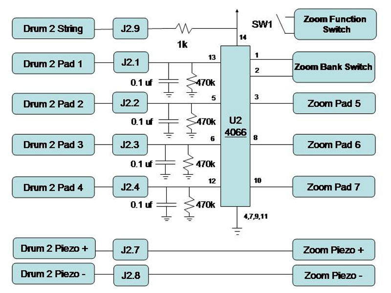
An electronic drum is basically a switch that triggers the playback of a digitally recorded drum. Here’s how I built tubular drum controllers out of PVC pipe and connected them to a studio drum machine to create a professional-sounding electronic drum kit. Each controller has a guitar string suspended above 4 strips of aluminum tape. When you strike the string with a drumstick, it touches the tape and closes a circuit to trigger the corresponding sound from the drum machine. Foam covering the pipe softens the blow and provides a nice bounce. Underneath each controller, a pressure-sensitive piezoelectric device lifted out of the drum machine detects the force of the hit, to determine the relative volume.

The brief contact between the struck string and the foil is too short for the drum machine to detect, so a pulse-stretching circuit lengthens the signal, by charging a capacitor. Two male-to-female serial cables let you unplug the controllers from the drum machine. I cut the cables in half and connected them to the controllers and the drum machine. To plug-and-play, you simply mate each connector to its former other half.

Project Steps

Build the controller bodies.

Note: Our Zoom MRT-3B drum machine has 7 trigger pads and 1 bank select switch. We’ll make 2 controllers to drive it, each with 4 pads. For simplicity, I’ll describe building 1 controller; just double each step to make both. The controllers are physically identical, but we’ll wire them slightly differently later.

Draw a reference line straight down the PVC pipe; a doorjamb makes a good guide. Cut five 3″ pieces each of vinyl and polyethylene tubing, then insert the polyethylene pieces into the vinyl pieces and thread a cable tie through each. These spacers will flank each drum pad.

Center a 30″x3″ strip of foam over the pipe’s reference line and secure it down with 5 spacers, spaced 7″ apart. Make sure the foam lies flat. Stick four 6″ strips of foil tape to the foam, centering them between the spacers and avoiding wrinkles.

Orient the pipe left-to-right, the way you’ll play it. Along the reference line at the left end, drill a 1/4″ hole 1″ from the end, and file a 1/16″-wide slot going 1/2″ to the right.

At the right end, drill a  1/4″ hole along the line 1 1/2″ from the end, and another  1/4″ hole, for the tuning peg, on the far side of the pipe, 90° around from the line and 3/4″ from the end. Drill 1/16″ pilot holes and install the tuning peg with the screws that came with it. Don’t overtighten or you’ll strip the threads. Drill a 1″ hole near the upper left corner of each foil pad, outside the foam and next to its adjacent cable tie.

Mount the pipe to its base by turning it over and attaching the wood with 3 lag screws in countersunk holes. Solder a 6″ wire to a guitar string’s brass ring and slide the rubber stoppers, large ends pointing toward each other, onto the string. Pass the wire through the slotted hole in the pipe, and anchor it by sliding the brass ring under the slot. Feed the other end of the string down through the hole at the opposite end and thread it onto the tuning peg inside. Slide 1 stopper to each end, and tighten the string so that it doesn’t touch the foil.

Connect the pads.

Feed a wire through each of the 1/8″ foil pad holes and out the left end of the pipe. Strip 3″ of insulation off the pad-side wires, lay the bare copper along the edge of its foil pad, and tape it down with a  1/4″-wide strip of foil tape.

Note: The adhesive on the bottom of the foil is non-conductive, so the copper wire must touch the top surface of the pad foil.

Cut a serial cable in half. Take the female half and tie a knot 6″ from the cut end. Use solder and heat-shrink tubing to connect the pad wires to the wires for serial pins 1, 2, 3, and 4, as specified in the schematic diagram. Pads are numbered from left to right. Use a multimeter to associate the wires in the cable with the corresponding pins on the connector.

Connect the piezo elements.

The Zoom MRT-3B drum machine has 2 pressure-sensitive piezoelectric elements that detect the force of pushes on its drum pad buttons. We’ll remove them and put 1 underneath each pipe, so that they’ll perform the same function there.

TIP: Download a disassembly video to see how the Zoom MRT-3B comes apart.

Pry the volume knob off the drum machine and unscrew and remove the back of the case. Remove the 4 screws inside that hold the battery case and the 2 screws on the MIDI connector. Write down where they go, and save them in a cup.

The piezo elements are the disks behind the circuit board from the drum pad buttons. Unsolder both and gently remove them. Solder and heat-shrink two 36″ wires to each, and thread the wires through the side pad hole near the middle of each pipe. Slip the piezo element between the pipe and the wood, but don’t force it, or it will crack. Encase the entire piezo element and its wires in silicone sealer and let it set overnight.

Following the schematic, connect the piezo’s red wire to serial cable pin 7 and its black wire to pin 8. Also connect the string wire to pin 9. This completes the controller’s serial cable connections. Drill two  1/4″ holes, one above the other, about 1/2″ from the end of the pipe, and cable-tie the serial cable knot to the inside of the pipe.

Wire up the drum machine.

Push the power switch into the case to dislodge the top circuit board, then unfold it to expose the board underneath. Remove the remaining screws, lift the boards from the case, and remove the white silicone pad membrane from the board along with the buttons, pads, and display. Gently sand the carbon coating off the top right corner dot of the switch pad contacts to reveal copper pads.

Caution: Don’t rub too hard or you’ll scrape away the pads themselves.

Solder 12″ lengths of 30-gauge wire to the right contact of each drum pad, and pairs of wires to the Pad Bank and Function switches. Replace the circuit boards in the case and thread the wires out the pad holes in front. Solder wire pairs to the power pads and to each of the piezo element pads on the back of the circuit boards and thread those out the front as well. Reassemble the drum machine in its case.

Build the pulse-stretching circuits.

Trim the mini PC board to fit in the project box. Clean its copper pads with a pencil eraser and solder a socket into the middle of each half.

Follow the schematic to build the rest: connect the controller wires from the serial cable to the quad switch’s control pins (pins 5, 6, 12, and 13), hanging a grounded 470kΩ resistor and 0.1µF capacitor off of each. Connect the quad switch’s V+ (pin 14) to the controller’s string (serial cable pin 9) through a 1kΩ resistor.

Ground the specified quad switch pins. Finally, install both 4066 chips in the sockets.

Connect the drum machine.

Bolt the project box to the drum machine, pass the male serial cables through  1/4″ holes drilled in the sides, and strain-relieve them with cable ties. Mount the push-button switch on the side of the project box and solder it to the pair of wires from the drum machine’s Function switch.

Follow the online schematic to connect the rest: solder the +V (pin 14) and Ground (pin 7) of one of the 4066 chips to the V+ Power and Ground of the drum machine circuit board. Connect the pad button leads to the quad switches’ signal pins. Connect the Pad Bank leads to pins 1 and 2 of controller #2.

Plug the 2 drum controllers into the circuit, and you’re ready to play. The circuit gets its power from the drum machine, so you should see its LEDs light up when you hit each pad. If they don’t, swap controller cables to determine whether the problem is with the controller or the circuit. Since we wired directly to the pads, all the functions of the drum machine will still work. Pad 5 controls the Bank select. Strike it to select an alternate drum set.

Enjoy your electronic drum set. Bust out some beats and start a band!

Conclusion

This project originally appeared in MAKE Magazine Volume 15.