Here you will learn how to wire the Arduino clone up and how to start your first project. In this tutorial, I am working with a breadboardable ATMega Lite Dev Kit from SurplusGizmos.com, but this can apply to other Arduino clones, too, such as the Ardweeny kit in the Maker Shed.

Note: this tutorial is meant to be followed after you have soldered your Arduino clone together. Now, without further ado, let’s dive in!

Project Steps

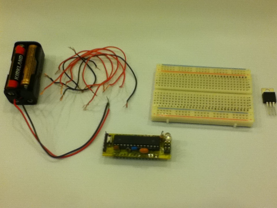
WARNING: ATTEMPT AT YOUR OWN RISK! I have found that my Arduino clone is partially dysfunctional (will run TV and LED, but not speaker or LCD). Here are the parts that you will need. They are, from left to right, a 6 or 9 volt battery pack, misc. wire, an Arduino clone, a breadboard, and a 7805 voltage regulator.

Place the Arduino clone on the breadboard, with one row of pins on either side of the breadboard.

Now, on the “front” side of the breadboard, next to the Arduino clone, place the 7805 chip with the heatsink facing away from you.

Next, let’s hook up the battery pack. Put the positive (red) probe into the same row as the far left pin of the 7805, and put the negative (black) probe into the negative bus (the line of pins with the blue line over it). Also, run a wire from the row with the middle pin of the 7805 to the negative bus, and run a wire from the right pin to the positive bus.

It’s starting to get a tad more complex. Run wires from the positive bus to the rows with the pins labeled “VCC” and “AV,” and run wires from the negative bus to the rows with both of the “GND” pins.

Nice job! The LED on the board should light up. If it doesn’t, make sure that you have done all of the steps correctly, and that you soldered your clone correctly. Now, assemble a “parallel programmer,” which is a device that hooks into a Windows or Linux computer (if it originally ran Windows) that will program this device. If you have a AVRISP or other programmer, then use that instead. Here is how to build a parallel programmer.

Now, let’s build our first project! Collect the parts shown (LED, wire, and 330 ohm resistor).

See the wire on the right? Connect a wire from one negative bus to the other.

Now add a resistor from either pin 13 or pin B5 (depending on the model of your Arduino clone), and connect it off to a row with nothing else on it.

Last step before programming: place the long (+) probe of the LED into the same row as the resistor, and the short (-) probe into the new negative bus.

Here’s an easy step. Once the parallel programmer is finished, just hook in into the back of your computer, and into the ISP pins on the Arduino clone (the 2×3 array of pins on the Arduino clone).

Now to working with the computer. On Windows, open Program Files, open the Arduino folder, and go into /hardware/Arduino/boards. (For Mac, check Applications, and for Linux, check where you installed it). Now, add this to the bottom of the file (retype it, it doesn’t copy correctly).

atmega328pp.name=Arduino Clone with Parallel Programmer atmega328pp.upload.protocol=stk500 atmega328pp.upload.maximum_size=30720 atmega328pp.upload.speed=57600 atmega328pp.upload.using=parallel atmega328pp.bootloader.low_fuses=0xFF atmega328pp.bootloader.high_fuses=0xDA atmega328pp.bootloader.extended_fuses=0x05 atmega328pp.bootloader.path=atmega atmega328pp.bootloader.file=ATmegaBOOT_168_atmega328pp.hex atmega328pp.bootloader.unlock_bits=0x3F atmega328pp.bootloader.lock_bits=0x0F atmega328pp.build.mcu=atmega328p atmega328pp.build.f_cpu=16000000L atmega328pp.build.core=arduino

Now, open the Arduino IDE (get this from http://arduino.cc), go into Tools -> Board, and select the option “Arduino Clone with Parallel Programmer.”

Finally, open the Blink program in the IDE (Open button, Basics, “Blink”), and download it onto the Arduino clone (Download button). If you are lucky, then you should be able to unplug the parallel programmer, and the LED should blink! Note: if you got any errors, make sure that the parallel programmer is not touching anything on your board and that you followed these steps correctly.

Congratulations! Look at the Arduino sample code and the tutorials on this website. For future reference: the pin that says “B0” = pin 8, “B1” = pin 9, etc.