This is an alternate build of the Brain Machine from the Maker Shed. I really like the Brain Machine, but I wanted to make a version that does not mount the electronics to the glasses.

Please note: Maggie is a highly trained electrical engineer, stunt-dog, and chemist. Please don’t use the Brain Machine on your average k-9. Thanks!

Project Steps

Build the Brain Machine kit from the Maker Shed.

I am not going to go through the process of making the Brain Machine. The kit comes with build instructions and links to online tutorials. This build is all about the modifications I did to the kit.

Preparing the Make Project Tin

The phone cord will connect the 2 LEDs on the glasses to the PCB that will be housed inside the Make Project Tin. Drill 1 hole based on the size of the grommet you will be using for the phone cord to pass through. The grommet is to protect the phone line from becoming frayed by the sharp edges of the hole you drilled. I used a 5/16″ grommet, so I drilled a 1/8″ pilot hole and followed up with a 5/16″ drill bit. Now, just add the grommet to the hole. Feed the phone line through the hole with the grommet. Next, tie a knot in the cord so it cannot slip through the hole.

Drill 2 more holes at the opposite end of the tin. One is for the new panel mount headphone jack, and the other is for the switch. The sizes depend on the size of the switch and headphone jack you were able to buy and/or scavenge.

Wire the Brain Machine

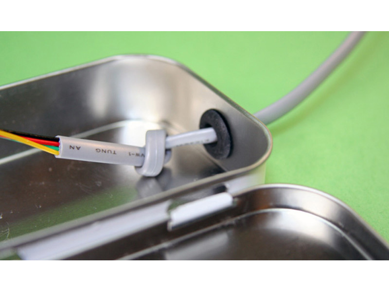
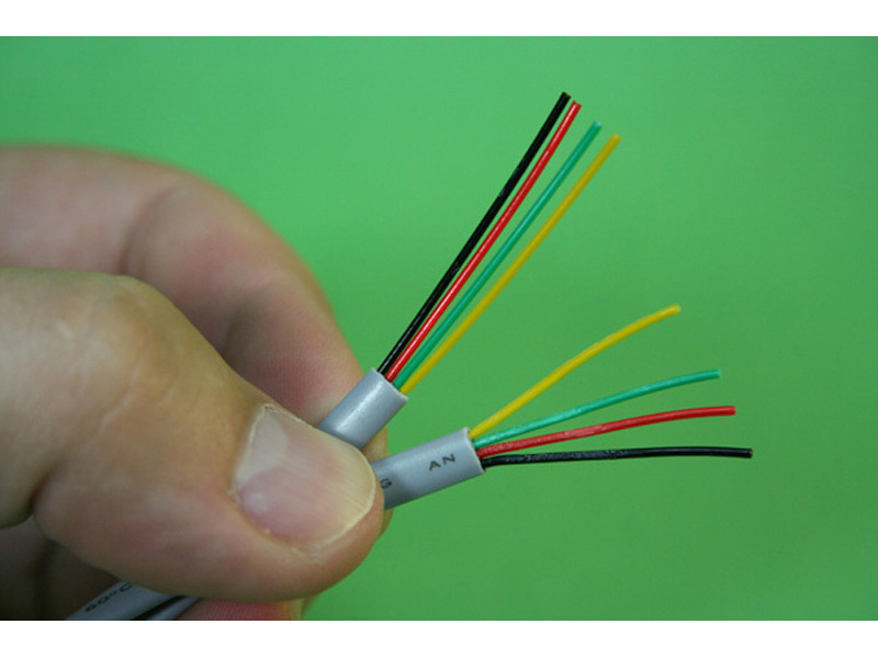
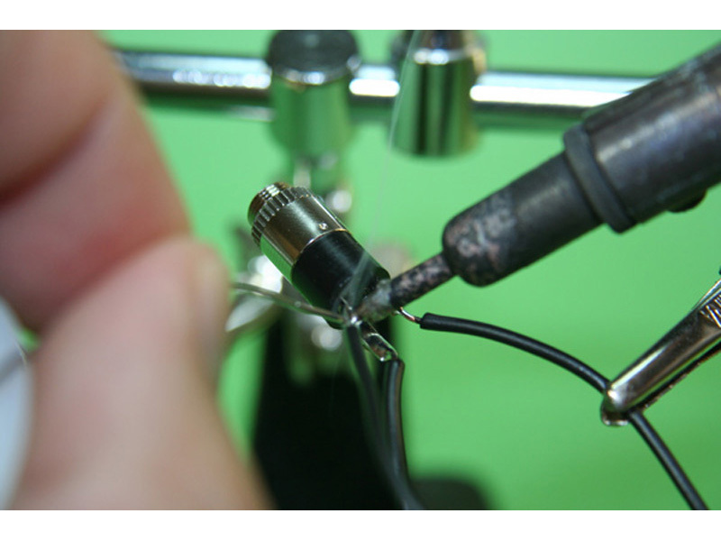
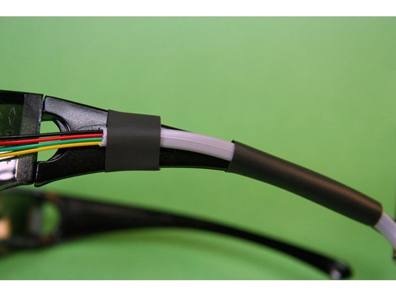
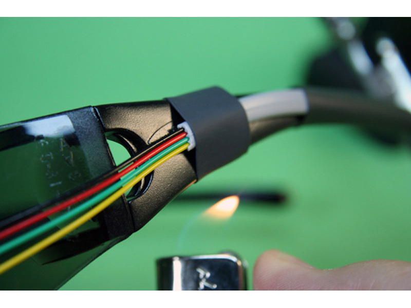
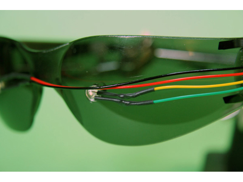
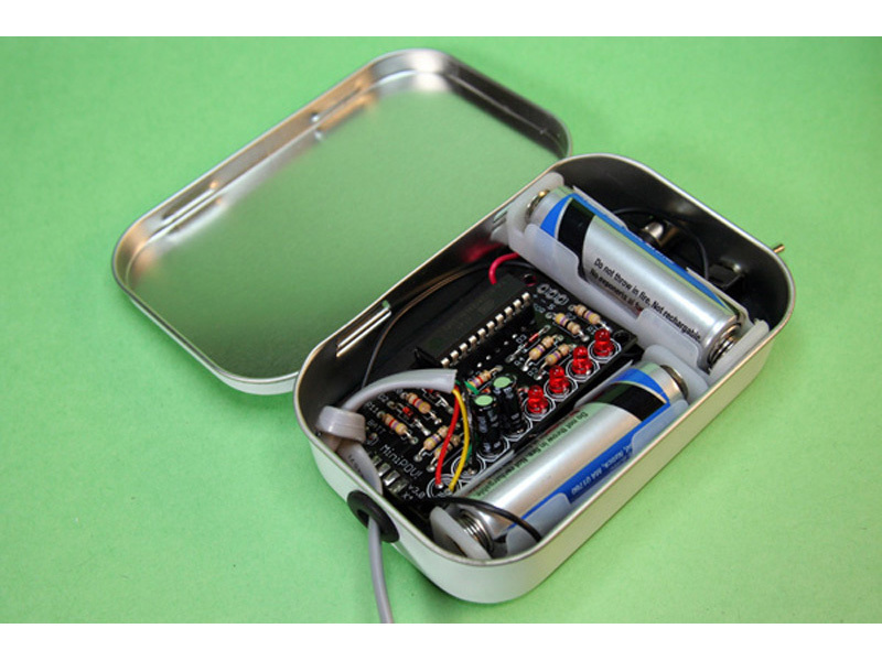
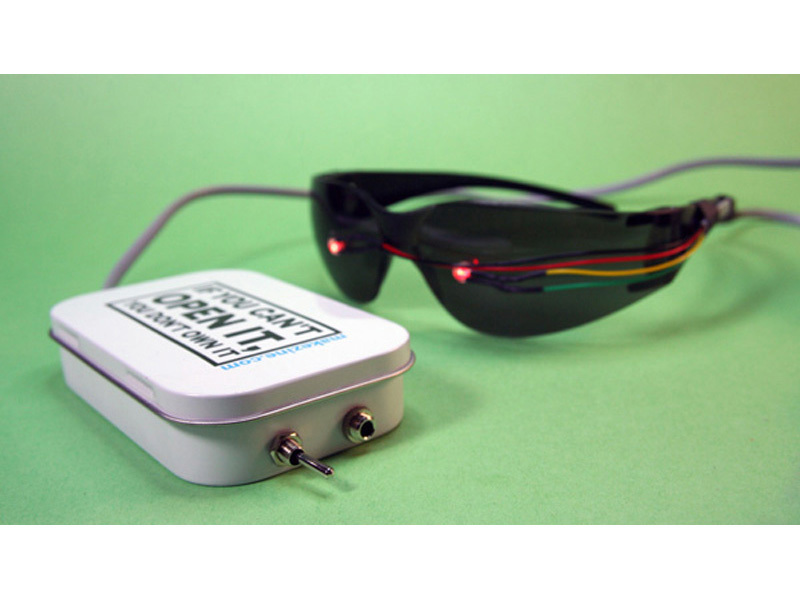
Start by adding the new, longer, wire to power the LEDs. I used 2-line phone cord approximately 4-6′ long. It is cheap, has 4 wires, and a lot of people may already have some in a parts bin. You can use any type of wire that you have, just make sure it has 4 wires and is long enough so you can wear the glasses and place the Make Project Tin on a table or your lap. Solder the wires as described in the instructions from the Brain Machine Kit.

Additional Modification [not necessary, but saves a lot of time]:

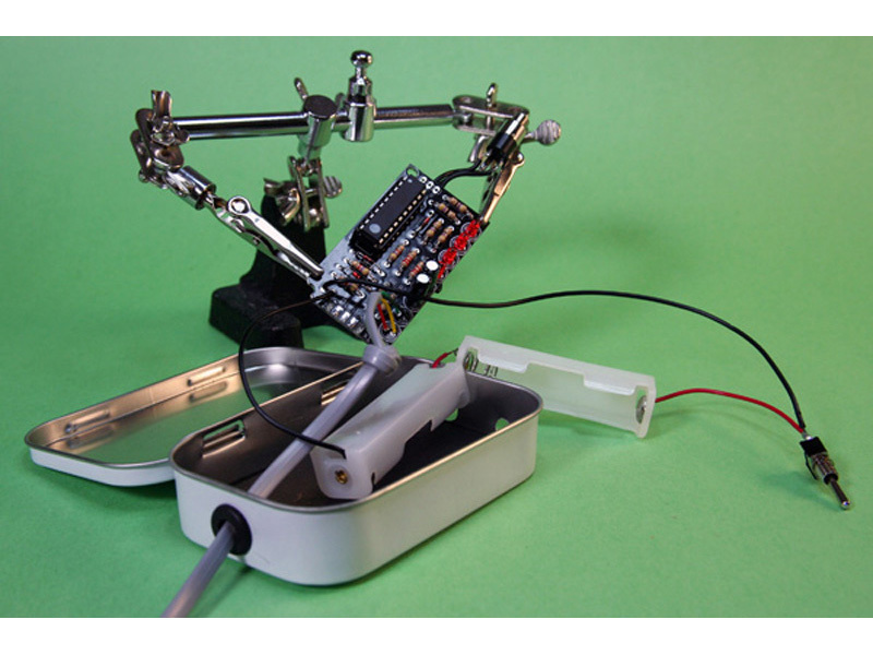
After programming your Brain Machine, you can de-solder the DB-9 female connector if you don’t want to cut a hole in the tin. I never plan on reprogramming the Brain Machine so removing the adapter is no big deal, and it saves me some time cutting the tin. If you want to keep it, just cut a rectangular opening in the Make Project tin and secure.

Soldering the additional components

Instead of using the included 3.5mm stereo jack, solder in the panel-mount barrel-type headphone jack. The wires attach the same way as the one included in the kit, so once again, follow the directions in the kit.

We need to split the batteries up so that they fit into the project tin. The following refers to the 2 new single AA battery holders. First, solder one red wire from battery holder #1 to one black wire from battery holder #2. Solder the remaining red wire from battery holder #2 to one of the terminals on the switch. Solder the remaining black wire from battery holder #1 to the “-” solder point on the Brain Machine. Finally solder a wire from the the other terminal on the switch to the “+” solder point on the Brain Machine. Got it? Great! (It sounds a lot worse than it is.)

Making the glasses

First decide where you are going to run the phone wire. I ran mine down one of the arms of the glasses. Make sure to allow a little extra wire so the glasses will close when you aren’t using the Brain Machine. Next, cut a piece of 3/8″ heat-shrink tubing approximately 1/2″ long and a piece of 1/4″ heat-shrink tubing approximately 3 1/2″ long. Thread the phone cord and the eyeglass arm through the tubing and secure.

Shrink away!

Solder the LED wires to the phone cord. They are wired the same way as described in the instructions. I used a little heat-shrink to make it look nicer and eliminate any shorts.

Stuff the Make Project Tin

First, cut a piece of card stock to fit the bottom of the tin. This will prevent any of the traces from shorting out if they come in contact with the metal tin. You must insulate the tin. If you don’t, your board will fry! Also, you can cut the corner of the PCB just a little so it fits in a little easier. You can see the trimmed PCB in the above picture.

Now all you have to do now is stuff it all in. Start by attaching the headphone jack and switch. The wires should go underneath one of the battery holders. Next add the 2 battery holders and circuit board. Now sit back, relax, and enjoy the show.