Based on my lifelong habit of “beatboxing” melodies and rhythms and essentially songwriting as I walk, drive, or shower, I’ve always wanted to make a device that would take my vocal mush and output exactly what’s in my head, in real time on stage.

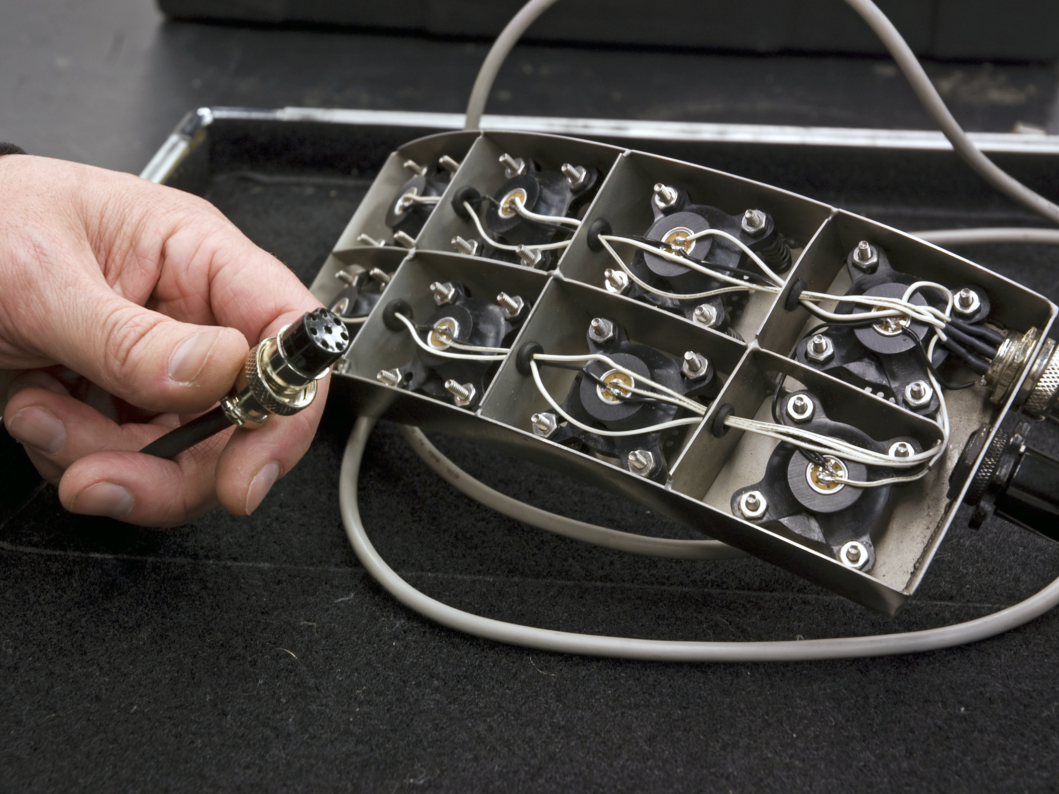
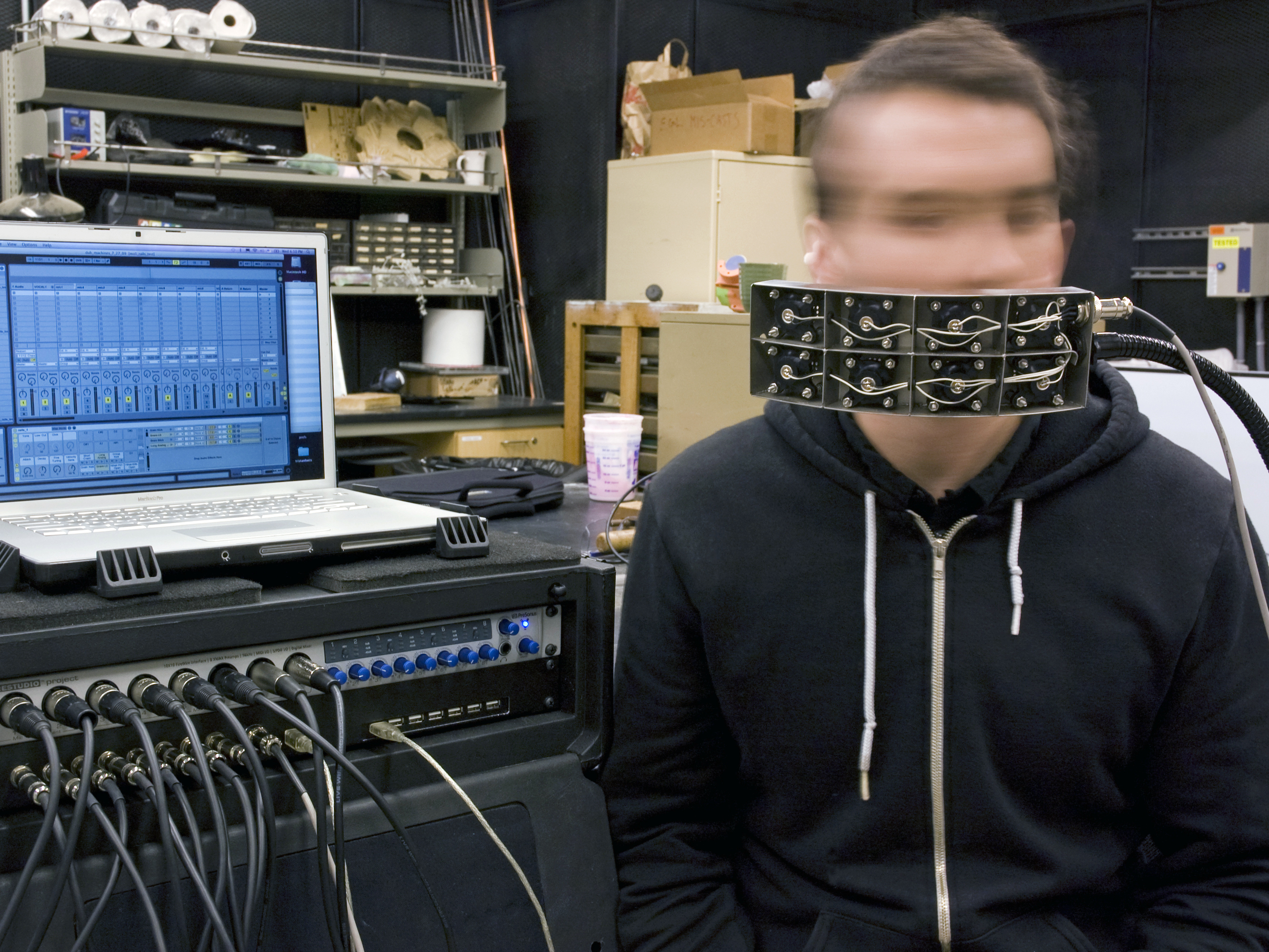
Well, I haven’t achieved exactly that yet, but I have created an 8-microphone input device that allows me to trigger or control 8 simultaneous sounds from music sequencing software (Ableton Live) as well as output 8 different mic/audio channels of my voice for input into the computer or mixer.

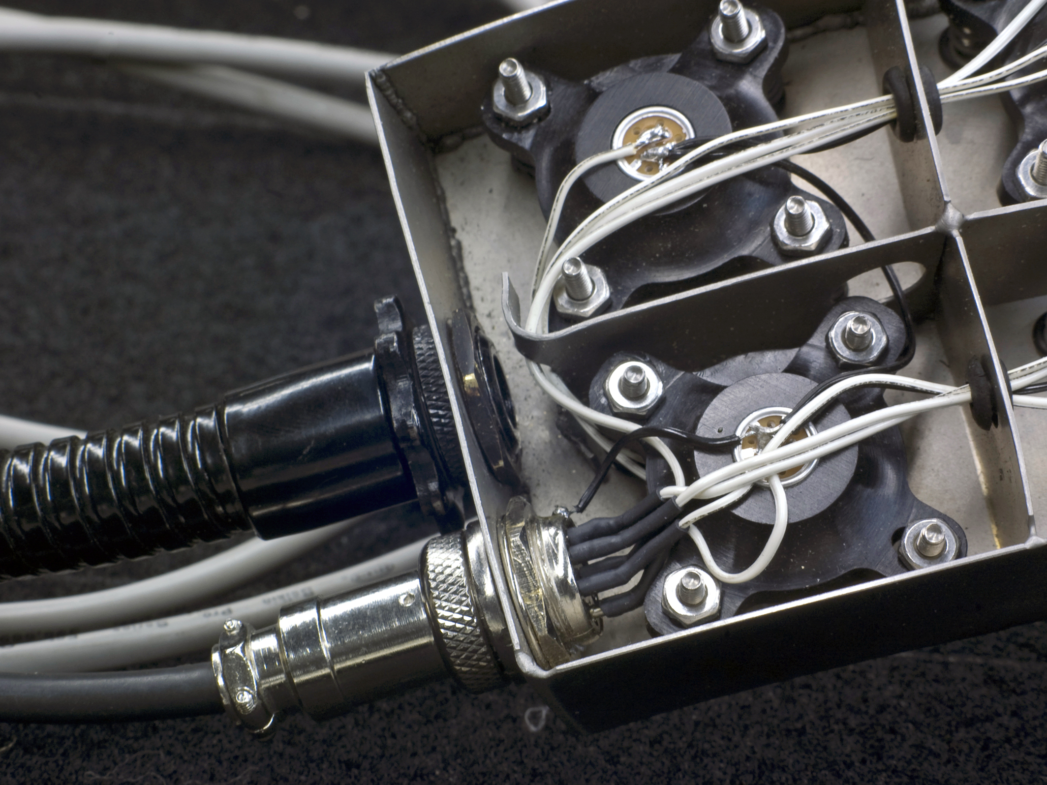
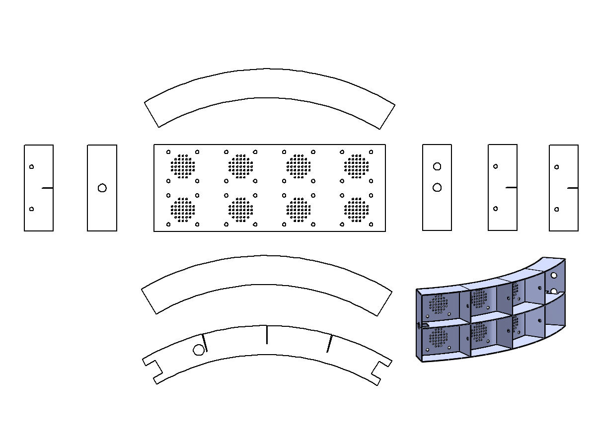
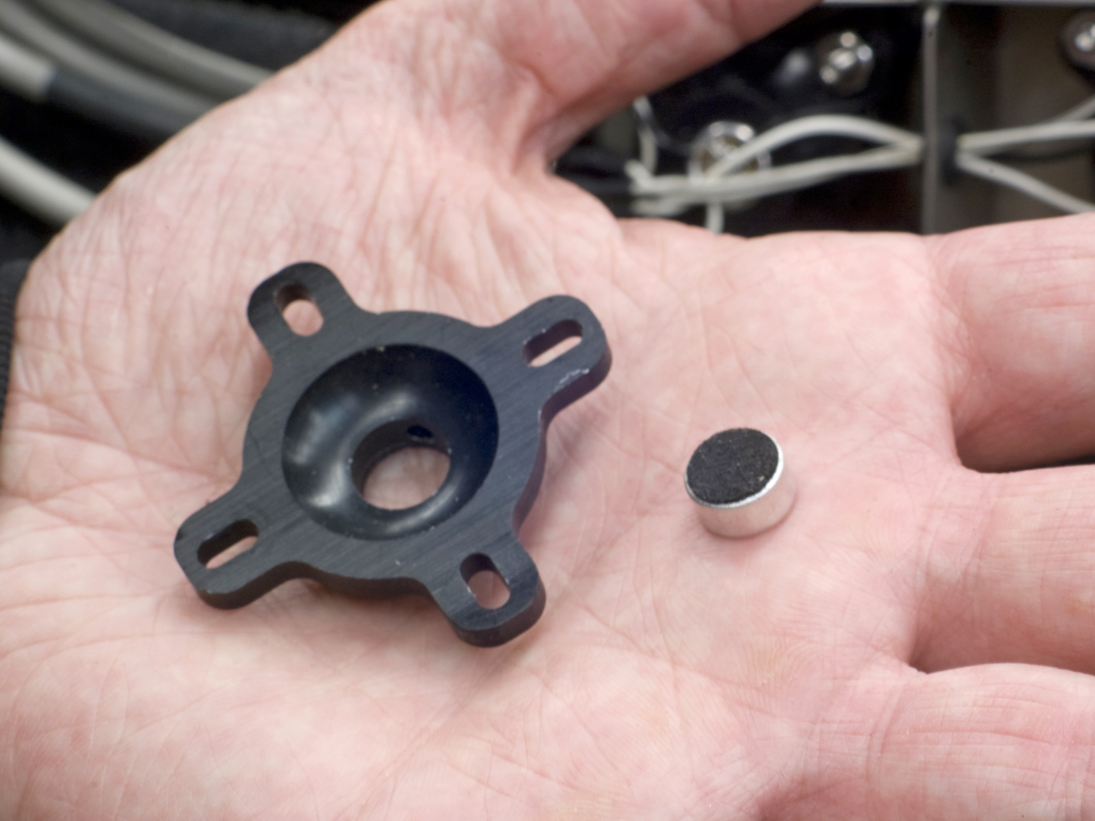
The 2 rows of 4 electret condenser microphones are unidirectional and compartmentalized, so there’s little cross-contamination of the audio inputs or vocals. Each microphone’s distance from your mouth is adjustable through a custom spring-loaded mechanism, and they’re close enough together that simply by turning your head or twitching a bit (much like a cat following a fly) you can easily place your mouth over any of them.

The brain of the Headgear is the Arduino Duemilanove microcontroller. The entire device (microcontroller and mics) is USB powered and has 8 mono microphone outputs. Since there are only 6 ADC (analog-to-digital converter) inputs on the Duemilanove, only the first 6 mic signals are used for MIDI triggering, but all 8 are live mic signals.

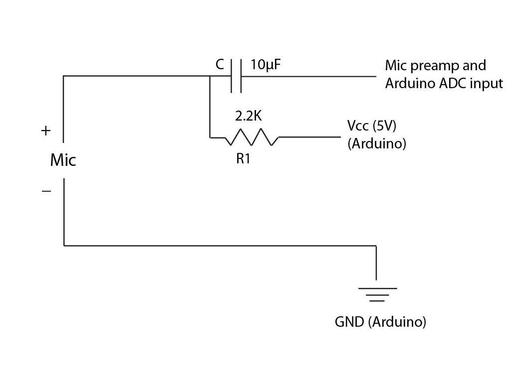
The signal from the microphones is split: it goes to the preamplifier as the audio signal that you hear, and also goes to the analog (ADC) pins of the Arduino. The Arduino converts the signal to serial data to send to a computer, and the computer uses the Serial-MIDI software to convert it into MIDI, which is then used by Ableton Live as a trigger to do whatever you want. The device is programmed to output MIDI commands to Ableton, but can easily be programmed to output OSC commands to communicate with Pd or Max/MSP.

NOTE: Some hard-to-find tools and materials in this design can easily be simplified. For example, the stainless steel cut and drilled with a water jet can be substituted with plastic cut with a razor blade and drilled with a normal drill.

Project Steps

Decide on a shape for the Headgear casing.

The first and most exciting part of this device (for me at least) is the shape. Since this is a sound controller using your mouth, think about how you want to move, what configuration your body will be in, and what your hands will be doing while you perform.

Design your Headgear based upon the movement and space limitations of your performance. This is the sculptural component of this project, so be creative!

The curvature of the Headgear matches the sweeping path of my mouth as I rotate my head, and the placement of the microphones allows me to basically tilt my head and rotate it ±60° (much like with a harmonica neck brace).

Make the Headgear frame.

First, choose your material. I chose stainless steel because it’s strong and, when polished, it’s not abrasive against the mouth as it glides from position to position.

Second, work out the envelope for the microphone placement. With your body within your self-defined performance limits, put a marker in your mouth and draw on a piece of paper placed in front of your face as you move your head; this defines the region where your mics can be placed.

Using this parameter, along with the shape you decided on, create your template for the Headgear frame, either by hand or using software such as Illustrator, SolidWorks, or SketchUp.

In your template, each mic “cell” should be isolated from the next by horizontal and vertical braces.

Also make sure to include small sound holes at the location of each mic, and four #4-40 machine screw clearance holes around each microphone location for attaching the mic cartridge mechanism.

The template shows the flattened Headgear shape with the braces and sides. I exported the drawings as .dxf files at 1:1 scale ratio and had the parts cut with a water jet.

If you don’t have access to a water jet or laser cutter, you can print the drawings out at 1:1 and use them as a template to cut out with a jigsaw and drill. The pieces can then be welded, or bonded with metallic tape or epoxy.

Mount the microphones.

Notice how I mounted the electret condenser microphone disk in each mic cell. A custom mic cartridge was designed and machined to fit the four #4-40×1″ machine screws, resting on top of the 4 springs and fastened with #4-40 nuts.

This design allows the distance of the mic from your mouth to be adjusted, which will change your signal/volume level. When mounted in the cartridge, the black foam side of the electret microphone disk faces toward your mouth.

Again, in place of the machined aluminum mic cartridge, you could use rubber bands, foam rubber, or any number of materials that allow you to mount to the 4 screws.

Wire up the microphones (Headgear side).

Using at least a 9-conductor cable, strip each wire at both ends. At one end, solder one wire to each of the 8 signal (not ground) solder lugs of the mics. Notice the ground pin on the mic in the photo is the one connected to the casing. Solder the ninth wire to one of the mic ground pins.

Then, using some extra wire, daisy-chain that last ground pin to the next mic ground pin, and so on, until all grounds are connected to the ninth wire and soldered together.

Build the microphone power circuitry.

There are many options for powering and amplifying electret condenser microphones (essentially the same mic in your laptop or in Britney Spears’ mobile mic). It comes down to how much time, headache, and money you want to invest. These mics tend to sound tinny to me, picking up every small drop and ping from my mouth — which is what I like about them.

The goal with the Headgear is twofold: to power the mic enough to input a decent line level into the FireWire mic preamp unit (I chose the PreSonus FireStudio because of its 8 mic preamps) and to make sure your max and min output signals are within 0V to 5V for input into the ADC pin on the Arduino microcontroller.

This way you get 2 sounds with one mic: your voice and the triggered sound (MIDI volume/expression is controlled by the loudness of your voice or ADC level). Here are the circuits you can use:

Option 1: Simple mic power circuit. Solder the circuit in the diagram onto the Arduino ProtoShield. Because of the circuit’s simplicity, all 8 of the powering circuits can fit onto one Proto-Shield. This circuit amplifies the incoming signal using the onboard USB power and outputs to the ADC pin of the Arduino and also the mic preamp of the FireWire device. Without an op-amp, the output is somewhere between 0V and 5V, but not exactly. I compensate for this in the Arduino code simply by setting limits, a quick and easy hack that works!

Option 2: Off-the-shelf circuit. For a more robust solution, create or buy the Amplified Mic op-amp circuit from SparkFun (https://makezine.com/go/SFcircuit). Soldering it yourself takes up a lot of space, so I recommend buying it, but SparkFun is nice enough to provide the schematic if you don’t want to buy their kit. This utilizes a rail-to-rail op-amp that ensures 0V–5V low to high signal.

Wire up the microphones (electronics side).

At the other end of the 9-conductor mic cable (the Arduino side), you need to solder each of the (+) mic signal wires into one of the 8 powering circuits created in Step 5, and the single (–) mic wire to ground. Arduino ground, mic preamp ground, and mic ground should all be the same. To reduce hum and buzzing, connect this ground to the rack mount frame.

Connect signal to the Arduino and mic preamp. The output of the powering circuit in is both your input signal to your preamp (usable vocal audio) and the analog input to your Arduino ADC pin(s).

Since the Arduino Duemilanove has only 6 ADC inputs, only the first 6 mic signals are used for MIDI triggering, but all 8 are live mic signals. An upgrade to the Arduino Mega or some additional circuitry would allow all 8 channels to trigger.

Get the software.

Three pieces of software are required to make the Headgear function: Arduino IDE, Serial-MIDI Converter, and Ableton Live (or the music sequencer of your choice).

Arduino IDE The Arduino IDE (Integrated Development Environment) software is a very user-friendly, C-like programming environment.

You need only a small amount of programming to read the ADC pins of the Arduino and then output the MIDI commands to trigger and control sounds; the code can be downloaded here.

Serial-MIDI Converter This software from Spikenzie Labs allows you to convert serial commands coming from the Arduino via USB into MIDI data that’s readable by music sequencing software without the need for a MIDI-to-USB adapter.

It’s very helpful to be able to both program and power your Arduino, as well as read MIDI, with a USB cable — no adapters or power cables. Download and follow the detailed instructions for setup here. This software must run in the background while Ableton is open in order for Ableton to recognize the MIDI input.

Ableton Live Within Ableton Live’s preferences, you need to select the device; the Headgear device will show up as IAC Driver, which is set up in the folder Utilities/Mac Audio MIDI Setup.

Once you select it, you can begin to map the Headgear MIDI to any parameters in Ableton, like drums or samples. You might need to play around with the actual MIDI command you have programmed on the Arduino (e.g., MIDI_TX(149,64,0)) so as to not interfere with other controllers. In addition to triggering, each of the 8 channels of vocal audio is fed into 8 different audio channels with different effects. Have fun!

Headgear as harmonica.

To use the Headgear as a “harmonica”-style drum machine, I use either the drum machine or the Impulse drum machine in Ableton. Both of these Ableton instruments are essentially samplers where you drop a sound/sample into a slot that’s actually a MIDI note.

You’ll need to figure out which MIDI notes your samples are on in the Ableton drum machine so that you can output the correct 6 MIDI commands from the Arduino (e.g., middle C is 60, so choose 60–65) to trigger 6 consecutive sounds. Once you have each of these 6 microphones triggering from your voice, you’ll need to make some adjustments based upon how you’ll use it.

If you’re controlling drum sounds, to prevent multiple triggers from one voice impulse, utilize the millis() command (a real-time timer) in the Arduino code to make sure not to trigger twice within a certain time frame (you can see how I’ve done this in my code).

With drum or rhythmic samples, you can play around with the mic order so that your head movement is optimized; for example, a configuration of upper left (kick drum), upper left inside (high hat), upper right inside (snare) creates a simple setup for basic beat making. For a more robotic movement, you can set up 4 samples in a row so that your head moves like a typewriter (my preferred setup).

If you intend to utilize both audio and triggering from a mic simultaneously (making a sound that might have an effect applied while triggering), you’ll need to play around with the millis() timer again in the C code to control how many times you trigger. In this case you might want to also adjust your analog input threshold.

Conclusion

This project first appeared in MAKE Volume 22, page 118.