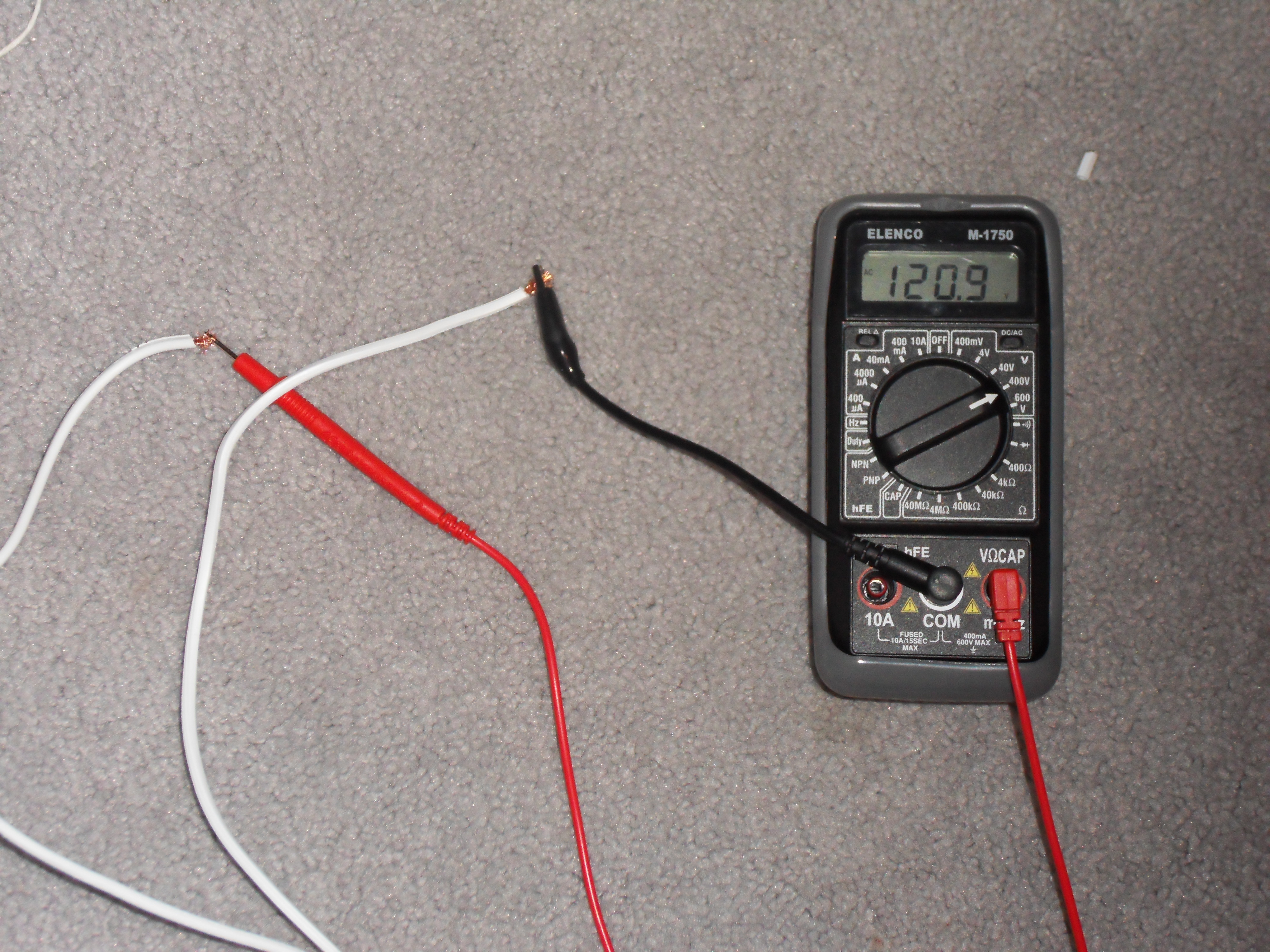
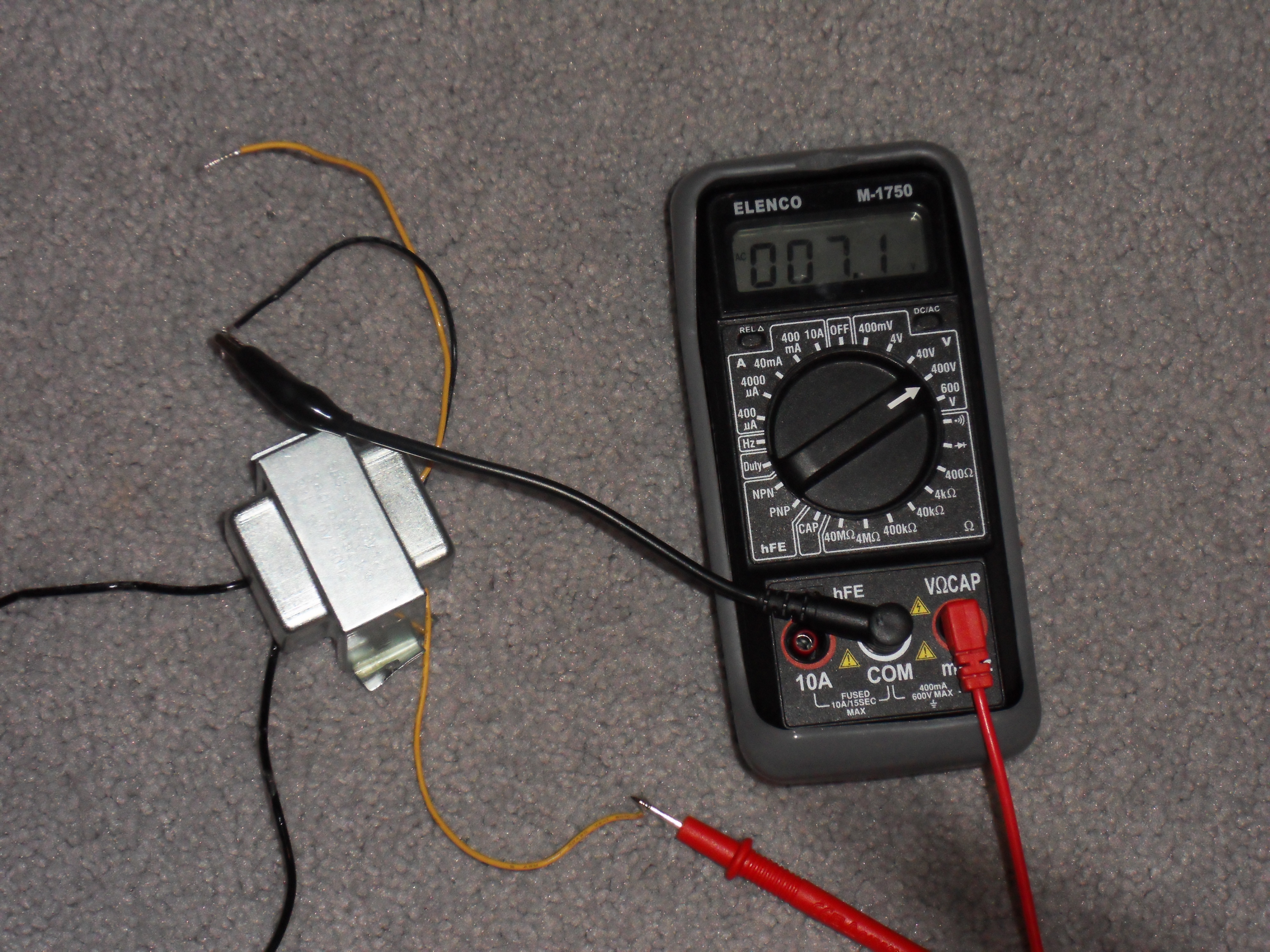
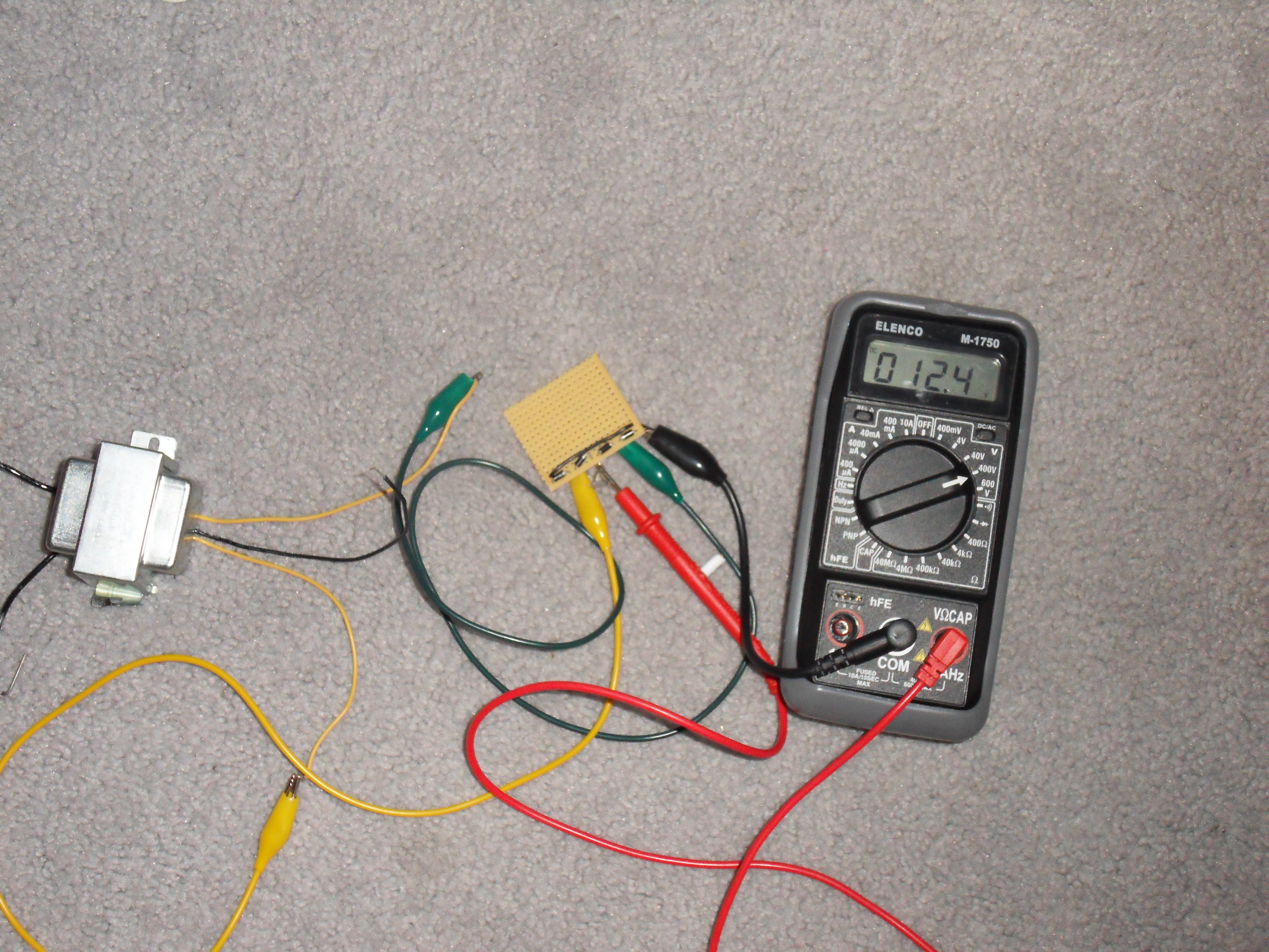
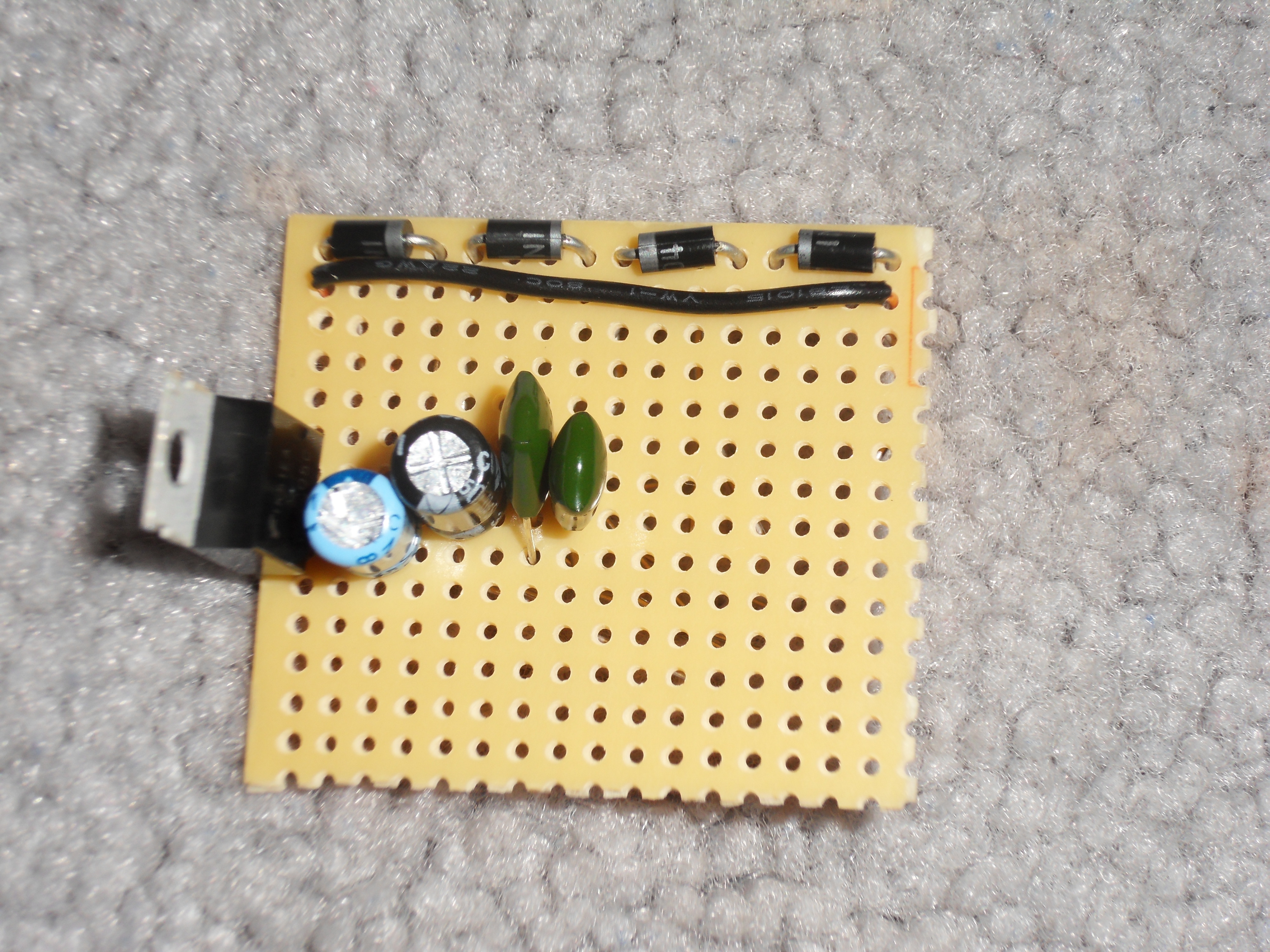
I like to build a lot of circuitry, but the voltage regulators that most IC’s require get annoying when you have to keep on buying them and putting them into each board you want to power. This is a very simple little device that will take the voltage coming from a power outlet in your home and change it into a steady 5v, good enough to power even the most picky of circuits.

Project Steps

Start by taking the extension cord and cutting off the end of it. If the power cord is grounded, then ignore the wire that leads to ground for now. Take your multimeter and measure the voltage across the hot and neutral wires, while the cord is plugged in.

The 120v AC coming from the frayed wire is very dangerous! Handle with extreme caution, as the amperage could kill you.

If this doesn’t work, something is wrong with your extension cord and you should use a different one.

Using alligator clips, hook up the hot and neutral ends of the extension cord to the primary leads of the transformer. With the multimeter, measure the voltage across one of the hot secondary leads and the neutral secondary lead.

If this voltage is higher than 9v, you’ll need a heat-sink for the voltage regulator.

Build the bridge rectifier

Break off a piece of perfboard at least 18×8. Sand the edges smooth.

If you have a preassembled bridge rectifier, you can skip this step. Insert four diodes across the top, with the cathode mark all facing toward the middle of the board. Strip a piece of wire and connect the anode (unmarked) side of the two diodes on the ends.

Now hook up the two hot secondary leads to the junction between the anode and cathode of two diodes, so there’s an anode and cathode connected to both of the secondary leads. Power up the transformer, and measure voltage DC: negative at the ends of the diodes, and positive at the middle of the diodes.

Assemble the voltage regulator

Insert the voltage regulator into the circuit, input facing the diodes, and solder it down. Push in one electrolytic capacitor and a film capacitor on the input lead and ground lead. Negative on the electrolytic connects to the common ground lead.

Push in and solder the other two capacitors on the output side where the electrolytic’s negative lead will attach to ground.

Test the circuit

Using a jumper wire, connect the input of the voltage regulator to the middle of the diodes and the common ground to either of the ends.

Hook up the transformer to the diodes (or bridge rectifier) again and test the voltage coming out of the voltage regulator. It should read a good 5v. If it doesn’t, power down and look for mistakes in the wiring.

If it does work, hook up a long red wire to the output of the voltage regulator and a black wire to anywhere that is connected to negative.

Mount it in a project box

Using electrical tape, wrap up the secondary neutral lead of the transformer, so that it doesn’t interfere with anything. Push the primary leads of the transformer out one of the holes and solder it to the extension cord, and then wrapping the joint in electrical tape.

You should now have a fully functional AC-to-5V wall adapter. Use it for whatever you like.

Conclusion

You should be able to run all circuits that require 5v off of this little device.