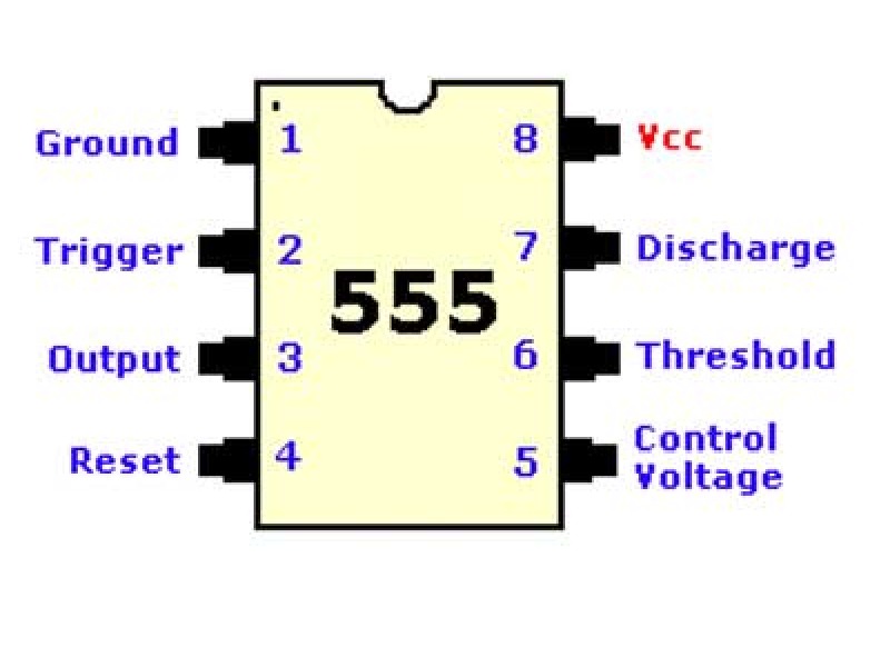
In this article, you will learn how to improve your collection of Snap Circuits blocks by adding a 555 Timer IC. You will learn the functions the pins on the 555 chip. You will learn that when the 555 is in astable mode, the output of pin 3 is a continuous stream of pulses called a square wave that can be heard on a piezoelectric speaker as a tone. Finally you will learn how to build an astable mode circuit for the 555.

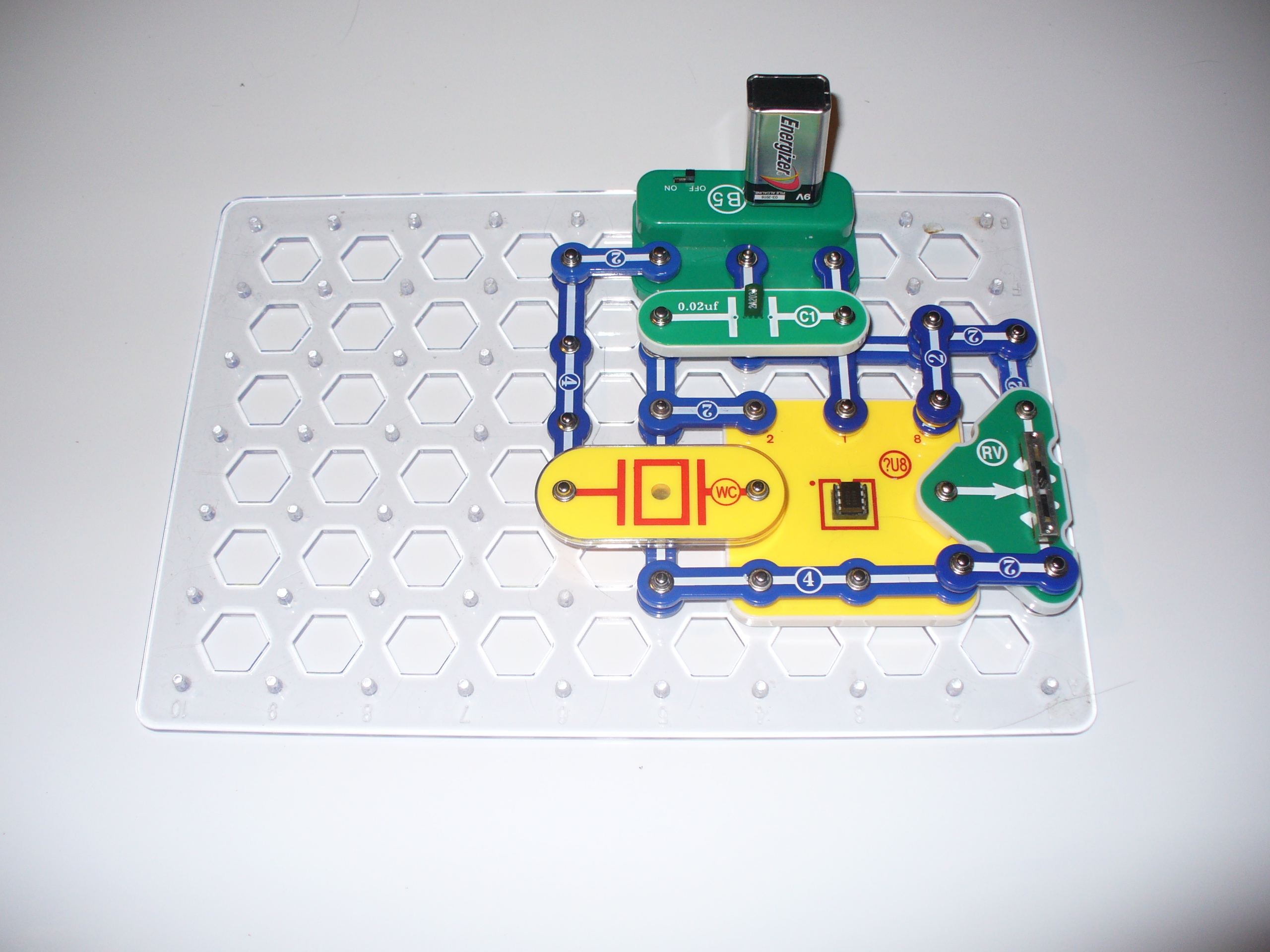
Snap Circuits is an educational toy that teaches electronics with solderless snap-together electronic components. Each component has the schematic symbol and a label printed on its plastic case that is color-coded for easy identification. They snap together with ordinary clothing snaps. The components also snap onto a 10 X 7 plastic base grid analogous to a solderless breadboard.

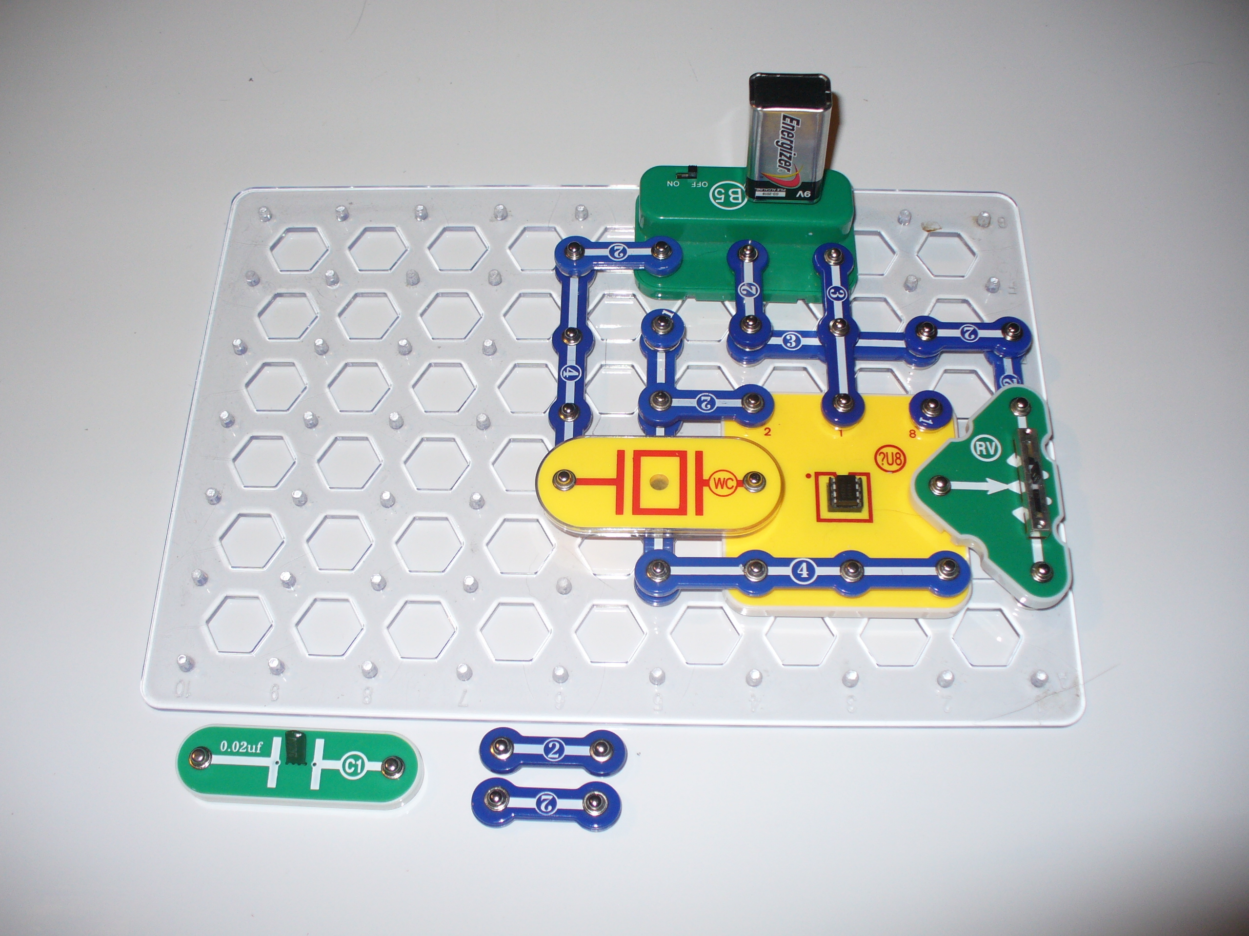
All the kits include manuals printed in color with easy-to-follow diagrams to assemble the projects. The illustrations for each project look almost exactly like what the components will look like on the base grid when finished. Because the electronic symbol is printed on each electronic component, once the project is completed, it will look almost exactly like an electronic schematic.

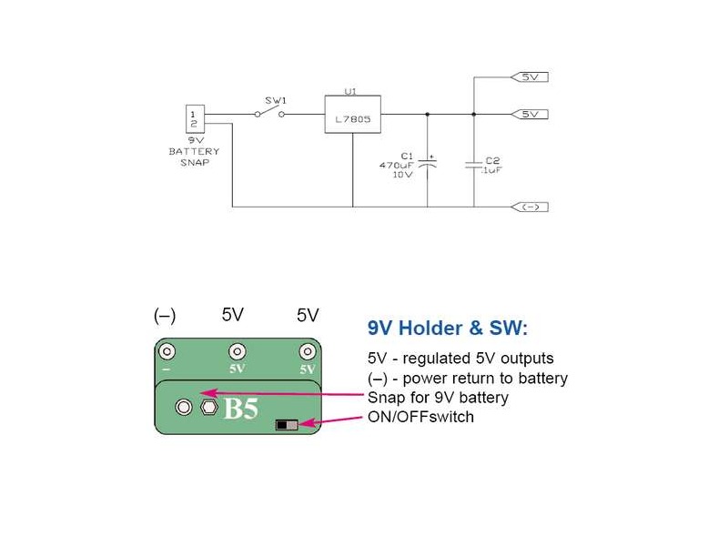
Currently there are no Snap Circuits sets that have the 555 Timer IC. So, you will need to purchase a 555 Timer IC from RadioShack. If you don’t have the Snap Circuits Extreme SC-750 set you can purchase the Snap Circuits Eight-Pin IC Socket block from C&S Sales. Adding these two components to your set of Snap Circuits blocks will allow you to create dozens of circuits built around the 555 Timer IC.

Project Steps

The 555 Timer IC was introduced by a company called Signetics (later bought out by Philips) in 1972 and was designed by Hans R. Camenzind in 1971.

The 555 chip has 25 transistors, 15 resistors and 2 diodes in an 8 pin DIP (Dual In-line Package) and looks like a square bug with eight legs.

It has a notch at the top and Pin 1 is in the top left corner.

Picture source

Insert the 555 timer chip into the Snap Circuits Eight-Pin IC Socket block (?U8). Make sure that the notch in the top of the 555 timer chip is aligned with the diagram of the chip pictured on the IC socket block.

Pin 1 is ground. It is connected to the negative side of your battery or power supply along with any other components in your circuit connected to ground.

Pin 2 is the Trigger pin. It will be connected to ground and thus switches on pins 3 and 7.

Pin 3 is the Output pin. In this circuit it outputs a square wave signal that can be heard on a speaker.

Pin 4 is the Reset pin. It is not used in this circuit.

Pin 5 is the Control pin. It is not used in this circuit.

Pin 6 is the Threshold pin. The capacitor that we will connect to the 555 will charge up and when it reaches about 2/3 Vcc (voltage from the battery), this is detected by the Threshold pin. This will end the timing interval and send 0v to the Output pin 3 (switch it off).

Pin 7 is the Discharge pin. It is also switched off by the Threshold pin 6. When switched off, it cuts the power to the capacitor causing it to discharge. Pin 7 also controls timing and is connected to the 50K ohm Variable Resistor RV. Moving the slider on RV changes the resistance thus changing the timing and the pitch heard on the speaker.

Pin 8 is connected to the positive side of your battery or power along with any other components in your circuit connected to positive.

Add the Snap Circuits blocks to the base grid as demonstrated in the picture.

Add the Snap Circuits blocks to the base grid as demonstrated in the picture.

Once you complete the circuit, switch on the 9 Volt Battery Holder (B5). You will hear a tone from the Whistle Chip. Move the slider on the Variable Resistor (RV) and you will hear the tone rise and lower in pitch depending on which way you move the slider.

The 555 chip is in “astable mode” which means that Pin 3 is sending a continuous stream of pulses called a square wave signal to the piezoelectric speaker (WC) that you hear as a tone. The square wave signal is caused by the charging and discharging of the capacitor. When you switch on the power:

Step 1. The capacitor charges up. When the charge in the capacitor reaches 2/3 Voltage, this is detected by pin 6, the Threshold pin.

Step 2. The Threshold pin 6 switches off the Output pin 3 and pin 7, the Discharge pin.

Step 3. When the Discharge pin 7 is switched off this cuts the power to the capacitor which causes it to discharge. When the discharging capacitor reaches 1/3 Vcc, this is detected by the Trigger pin 2.

Step 4. The Trigger pin 2 sends voltage from the battery to pin 3 (the Output pin) and same voltage to pin 7 (the Discharge pin) which causes the capacitor to charge up (go back to step 1).

This process repeats creating the square wave signal and you hear that signal from the speaker as a tone.

When you move the slider on the Variable Resistor (RV) this changes the resistance of the circuit. Since the Variable resistor is connected to pin 7, changing the resistance controls the timing of how often the capacitor charges and discharges which changes the pitch you hear from the speaker.

To power the 555, you can use the Snap Circuits B5 block (it is also called a 9 volt Holder and Switch). The advantage to using this block is that you can connect a standard 9 volt battery to the block and it will deliver a reliable 5 volts to the 555 through the L7805 voltage regulator circuit (see circuit schematic).

The B5 also has two 5 volt outputs–one to power the 555 circuit and one that you can use to power another device.