Neo Retro: We built this “Lixie” clock with just two digits, so it displays the hours and minutes alternately. The number 3 on the left is engraved as a single line, imitating the appearance of the original Nixie tube displays. Photo Credit: Andreas Wodrich

The legendary Nixie tubes are retro and cool — little glowing neon lamps that display numbers or symbols (Figure A). Too bad they’re no longer mass-produced, and the few that are still being made are quite expensive. In addition, they require sophisticated, high-voltage driver circuits. The good news: using multicolor LEDs and acrylic plates engraved with a laser cutter, you can re-create the Nixies’ retro charm, scale them up, and customize the design to your taste. In this project we’ll show you how to make a great-looking “LED Nixie” numeric display with illuminated digits, driven by an Arduino at a safe, cool 5V.

Figure A: Our LED-based replica doesn’t quite match the charm of a real Nixie tube, but is much easier to make, and more useful. Photo Credit: Thomas Saur

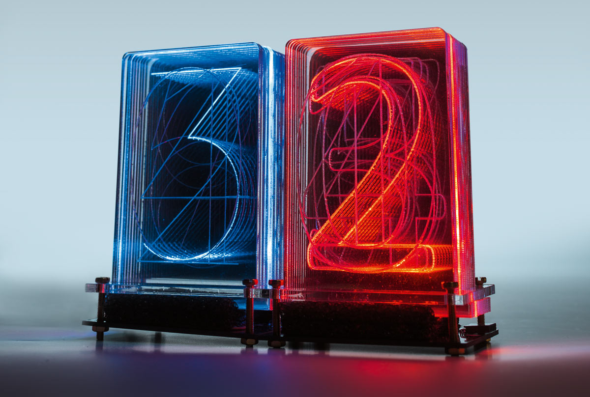
The working principle of the Nixie replica is simple, but effective: Ten transparent plates made out of extruded acrylic sheet (polymethyl methacrylate or PMMA, also known as Lucite, perspex, or plexiglass) are engraved with the numerals 0 to 9. Stacked on top of one another, each plate is illuminated from the edge using multicolor LEDs. Due to the internal refraction of light within the acrylic plate, only the numeral that’s selected will actually light up, while the plates’ surfaces, and all the other numerals in the stack, will remain transparent and colorless.

We didn’t come up with this idea — we’ve seen it demonstrated at Maker Faires in the U.S. and Europe. Connor Nishijima, a maker in Utah, coined the name “Lixie” for his projects, inspiring many other makers.

Our own design aims to show you how easy it is to build LED Nixies and make your own creations. You’ll need only basic Arduino skills, plus some soldering ability to populate the bare PCB.

Project Steps

Building an LED Nixie

The light from the LEDs on the circuit board shines into the tabs on the acrylic plate, which is engraved with a numeral. The foam mask on the board prevents the light from radiating sideways and straying into adjacent plates.

Because the light enters the acrylic from the edge, total internal reflection occurs, and the acrylic behaves like a light pipe. The light’s path is broken only at the engraved lines (and at the edges of the plate) so that only these spots light up — and the digit shines.

Laser Cutting

The cutting templates include 10 numeral plates and a clamping plate (single- or double-digit) to hold them all together. You’ll cut the red lines and etch the green lines (numerals). We chose two typefaces that we think work well. The thin type reminds us of the classic Nixie tubes, while the double-stroke type is more readable in brightly lit environments but conceals a bit more of the numerals further back in the stack.

We’re building a clock with our LED Nixies, so we need numbers, but there’s no limit to the type of letters, symbols, or designs you can use. Say you want to make a weather station that fetches its data over Wi-Fi. Your temperature display could be enhanced using a color range (say, blue to red), and you could use custom symbols for rain, clouds, sunshine, and thunderstorms.

Electronics

Pretty much all LED Nixies are based on WS2812B-type RGB LEDs, or the equivalent SK6812. These parts are popular as they can be controlled easily using very little hardware and code. Make sure to look for the “B” in WS2812B — this is a redesigned part with only four instead of six connectors on the SMD package. Adafruit offers various small boards using these LEDs in their NeoPixel line, and they provide a software library to control them from an Arduino.

Figure B: The decoupling capacitors next to each smart LED prevent voltage drops caused by large switching currents, just as you’d do for logic ICs.

While the Lixies we found on Tindie only have a single 1,000µF electrolytic capacitor in parallel to the LED power supply, we stuck to the datasheet (Figure B, above) and gave each LED its own 100nF (0.1µF) cap, as these parts aren’t just simple LEDs but also contain logic circuits. Adafruit’s NeoPixel Überguide gives an explanation of how the WS2812B LEDs work, and why you should absolutely include a 220Ω–500Ω resistor on the data line between your microcontroller and the first LED (Figure C, below). This resistor is not part of the circuit board, so you need to wire it to the data line.

Figure C: Make sure to include the resistor, and optionally provide a separate 5V power supply if you’re running more than two LED Nixies. You only need the RTC module if you’re building a clock.

To light up the numerals evenly, we use two RGB LEDs for each, spaced apart appropriately on the board: two LEDs for the 0, another two for the 1, and so on. This setup differs from the Lixie design, which is why the code is incompatible. (While each LED can be controlled individually, we typically use the same color for the two LEDs on each numeral.) The 20 LEDs comprising a Nixie “digit” form a unit, with a connector on the side where the next unit may be attached. Using this kind of cascade, you can easily connect 500 LEDs (25 LED Nixies), possibly even more.

The current drawn by a large number of LEDs may pose a problem, however. Each RGB LED may require up to 60mA if all three color components are set to maximum intensity. This adds up to 1.2A for a single LED Nixie — way too much for the outputs on an Arduino. But we’ll typically only light up one symbol per Nixie, so only two LEDs will be on at a time, drawing up to 120mA. Under these conditions, an Arduino can drive two LED Nixies. If your display needs more digits than that, you’ll have to provide a separate 5V power supply with sufficient output current.

Mechanical Construction

The male and female header connectors on the side of each LED Nixie are arranged so that they can easily be joined into a row. The Data Out pin from the last LED is wired both to the male “input” header and the female “output” header, so that it will connect to the input of the next Nixie. If you’re building a display with more than a few Nixies, you can improve its mechanical stability by attaching them all to a backplate.

As the LEDs’ beam angle is too wide for our thin acrylic plates, we need to focus them using a light grid made of foam (Figure D). The tabs on the numeral plates fit into the openings in the grid. They’re all held down by a clamping plate using four M3 screws; be careful not to let the tabs press directly on the sensitive LEDs.

Figure D: For each display unit (“digit”), you need a PCB, a light grid, 10 acrylic plates engraved with numerals, and a clamping plate to hold everything in place. The parts are joined using four screws. Photo Credit: Florian Schäffer

In our first attempts, we used anti-static ESD foam that we shaped using a laser cutter. (The template for cutting the foam is included in the downloads.) It took us quite a while to notice that this type of foam was making our prototype behave erratically — the signals controlling the LEDs were so delicate that even barely touching the conductive foam would cause malfunctions. We now use plain (non-conductive) foam, and our device works fine (Figure E).

Here’s our completed two-digit “Lixie” clock, with Arduino and RTC module. Photo Credit: Martina Bruns

Arduino Driver

To drive the LED Nixies, we used the Adafruit_NeoPixel.h library, which you can download and install using the Arduino IDE’s library manager. This library provides everything you need to drive chained WS2812B-type LEDs individually. When initializing a new instance, the constructor (see callout (1) on the code listing image below) is called with three arguments: the number of connected LEDs, the number of the I/O pin to use as data input, and what clock speed to use for data transmission. We added two functions that do all the work of controlling the individual LEDs to display a number on a chain of Nixie units, so you don’t have to.

The example code in led-nixie.ino shows how easy it is to display numbers. Two chained LED Nixies are connected to an Arduino. The DIGITS constant (2) must be set to the number of chained Nixie units you’re using. It’s used by the driver setup code as well as the code handling the calculations for the number display. The control PIN to be used is set in (3) and may be chosen arbitrarily (the default is pin 7). As soon as the code has been compiled and flashed onto the Arduino, you’ll see a looping display counting up from zero to 99, using random colors.

The OutNumber() function takes three arguments — the number to display, color to use, and a flag that controls whether leading zeroes should be shown — then splits the number into individual digits and sends them to the output, while checking how many digits can be displayed at all.

In our schematic in Figure C, we included a DS3231 real-time clock (RTC) module. Adafruit’s tutorial describes the use of this module and why it’s superior to the DS1307. To set the clock, you’ll hard-code the current time into led-nixie_clock.ino, compile, and flash. The Arduino will pass the time to the RTC, which stores it locally thereafter. You’ll then want to comment out the part of the code that sets the clock, so the RTC won’t be reset to the old time on each reboot. Your two-digit clock will display hours and minutes alternately, using changing colors.

Chopping Up Numbers

When displaying numbers, you’ll often encounter the problem that a lot of displays can’t directly take multi-digit numbers as input. The number needs to be split apart, so that each individual display will light up with the respective digit value for each position (ones, tens, hundreds, and so on). To achieve this, we’ll use a simple trick involving division.

Let’s chop up a three-digit number into its three digits: hundreds, tens, and ones. First we divide the original value by 100 (4) and then divide the result by 10 to find the remainder (this is known as a modulo operation, using the % operator) (5). So, to split up the number 201, division by 100 gives 2.01, and this modulo 10 gives 2, the last digit before the decimal point, and the right value for the hundreds. This result is passed onto the output routine (6). In the next step (tens), the original number is divided by 10 (7) (20.1), and the result of this modulo 10 (8)  gives us 0 for the tens. To get the ones, the original number is just taken modulo 10 (9), which results in the digit value 1. (We’ve used decimals here for illustrative purposes; the Arduino actually does the math with whole integers only.)

Play With Your Digital Display

Your LED Nixies are ready for the world! Use them for clocks and countdowns, hit counters and scoreboards, gauges and meters of all kinds — or whatever idea you’ve got. And if you’re not keen on building them from scratch, you can order them ready-made from makers like Connor Nishijima and LED-Genial and incorporate them into your projects that way.

We look forward to hearing your ideas for using LED Nixies, and seeing your designs for custom display symbols, especially very small or very large ones! Share your projects at makershare.com, and then let us know in the comments below.

Photo Credit: Andreas Wodrich

Originally published in Make: German edition, issue 4/2018. This article appeared in Make: Vol 66. Translation by Niq Oltman.