


LEDs are everywhere and in every project you see anywhere. They show that your microprocessor unit is alive and running the program you wrote. LEDs are tough little lights that light up everything including you. They provide instant gratification. Here is my simple tester. There are lots of kits to show you electronics and soldering and a lot of them use LEDs. Even high-end electronics use LEDs that nobody ever sees to tell a technician that a circuit is working.
Projects from Make: Magazine
LED Testing
Here are a few tools to make testing LEDs and other things easier. LEDs are so much fun.
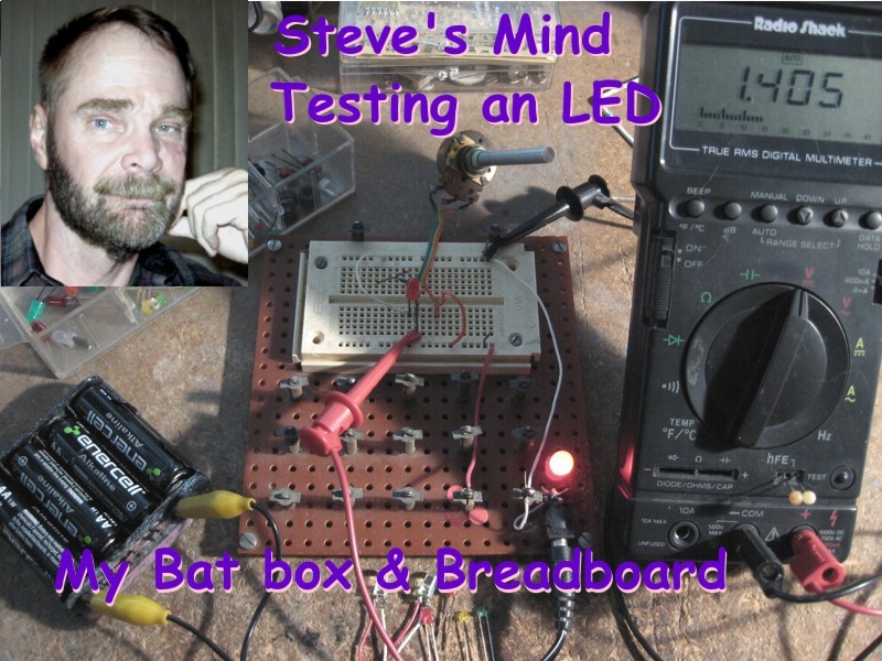

Build the circuit as shown in the picture. Always wire the pot so that clockwise rotation increases the voltage or lessens the resistance.
Wiring connections: Ground to LED–; Pot-2 to LED+; Pot-3 to Volts+; DMM to DC Volts; DMM– to ground; DMM+ to LED+.
Turn the pot counter-clockwise all of the way. Connect power.
LEDs are Current Devices and they have three states. 1: Lit but dim. Low light voltage. Saves batteries. 2: Lit and steady. Normal brightness. 3: Too bright. You are over-driving them and they will burn out sooner. Lastly, state 4: Too bright and dimming. You have just killed an LED.
Rotate the pot clockwise until the LED begins to light. You can note this as the lowest voltage that will light the LED. Note the voltage on the DVM. Keep the voltage to less than 2.2 volts for most LEDs.
Keep watching the LED as you are turning the pot clockwise until the LED brightness is steady. This is your LED’s operating voltage. Turn the pot counter-clockwise to the lowest point where the brightness of the LED is steady. This voltage will make the LED last longer.
Turn the pot too far and the LED will start to dim. Just turn the pot counter-clockwise until the LED brightness is steady. Keep the voltage at about 2 volts for maximum brightness for most LEDs.
Some LEDs have a circuit in them that controls voltage and current to the LED. They will not light until they have reached their normal operating voltage. They come on and stay at their normal brightness over a wide range of voltage and current. Usually this is between 4 and 12 volts.

Batteries can produce a lot of current, so test LEDs as shown and use the largest resistor you can for the best brightness. Normal LEDs run about 7 – 30~ milli-amperes (mA) each. Some high-brightness LEDs and LEDs with chips in them can draw 200 mA each. Above 5 volts I usually use a 460 – 1000 (1K) ohm resistor for normal LEDs and 22 – 200 ohms for high-brightness LEDs or LEDs with chips. The idea is to protect your LEDs for a longer life.
Limiting the current through each LED with a resistor on the positive lead will give your projects a longer life. It does not save your batteries. Lowering the brightness of your LEDs can save your batteries a little.
Current testing: Testing the current drawn by the LED is a better test for a current-driven LED. Replace the red wire from Pot-2 to LED+ with a second DMM or use the same DMM as shown.

Run Step 1 and note how the voltage changes slowly, but when you hit the operating voltage of the LED the current will jump up to the normal current of the LED. As you increase the current the brightness of the LED will start to dim. Turn the pot counter-clockwise until the current and the brightness is steady. Always keep the current on the low side and your LEDs will last longer.
Repeat for more LEDs.
Finding the resistor for the LED at that voltage:
Disconnect Power
Set DMM to Ohms. Disconnect the pot.
Measure across Pot-2 and Pot-3 to get the resistor you will need for that LED at that voltage. Find the closest higher resistor for your LED. Keeping the current lower will keep the LED healthy. Remember, the brighter the LED the shorter its life will be.
Reconnect the pot.
Turn the pot full counter-clockwise. Repeat the above steps for more LEDs.
Conclusion
LEDs light the world up and they are easy and fun.


