Supplemental adapting is the goal for this project.

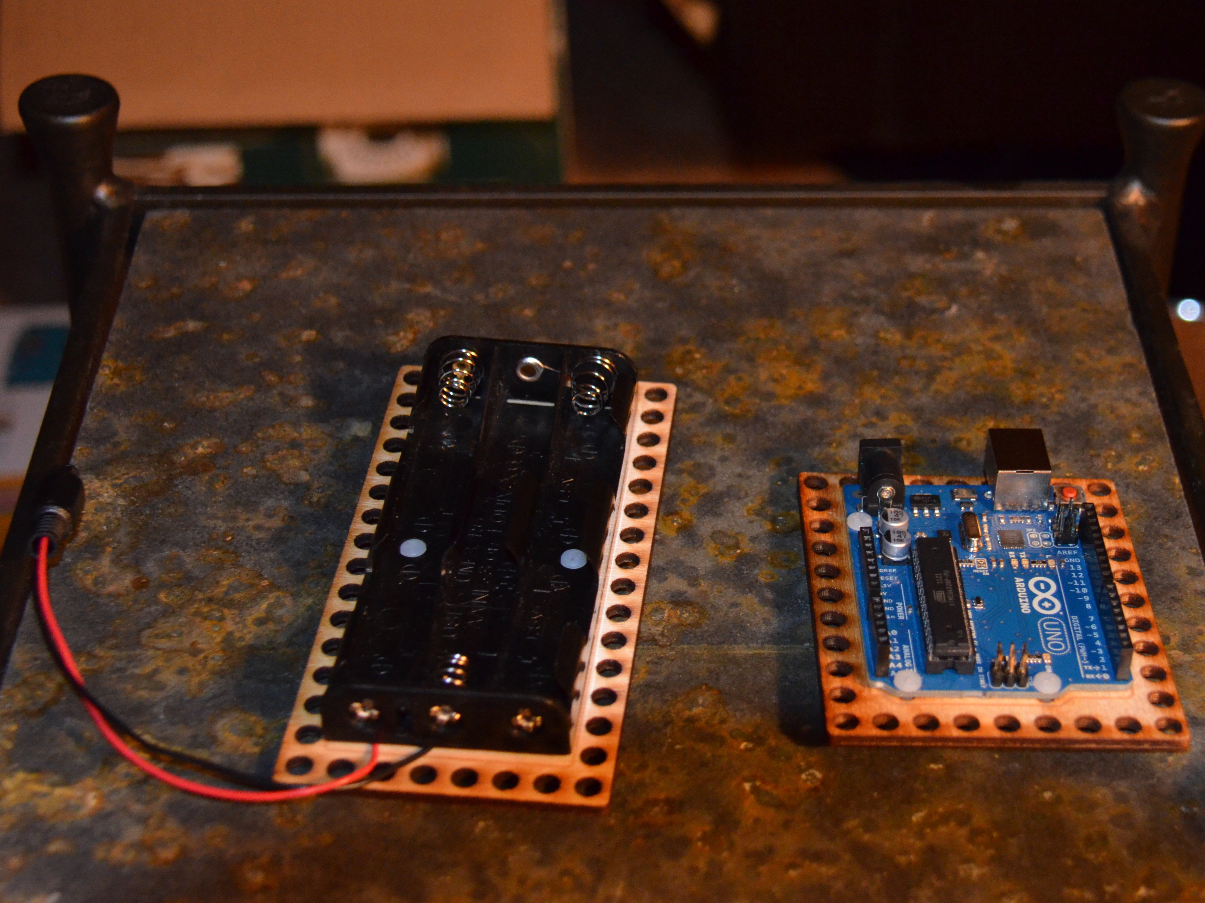
If you have ever taken a new adaptor board and tried to use it without thinking through its integration into a project you will know well that it is often only a first step.

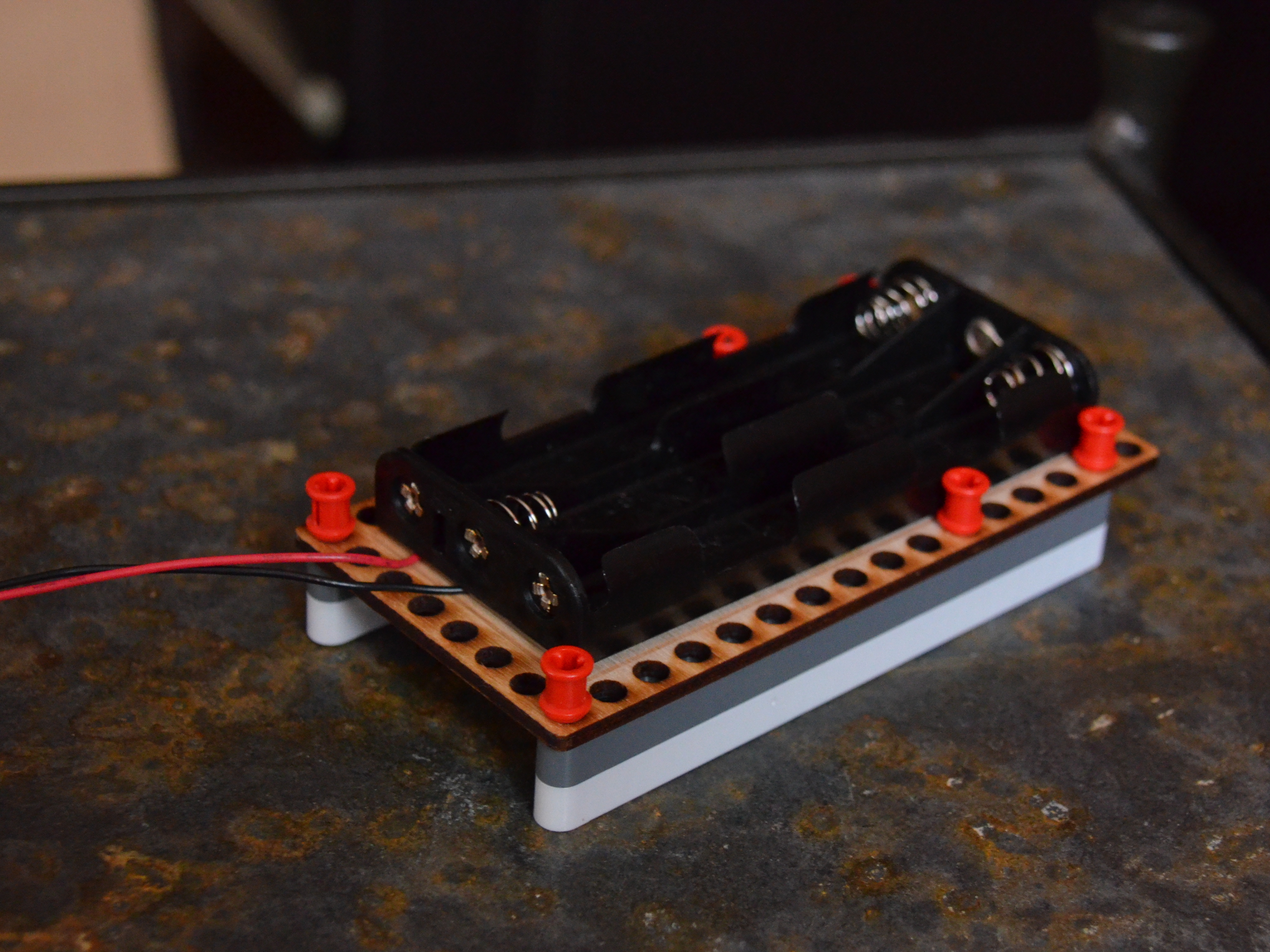
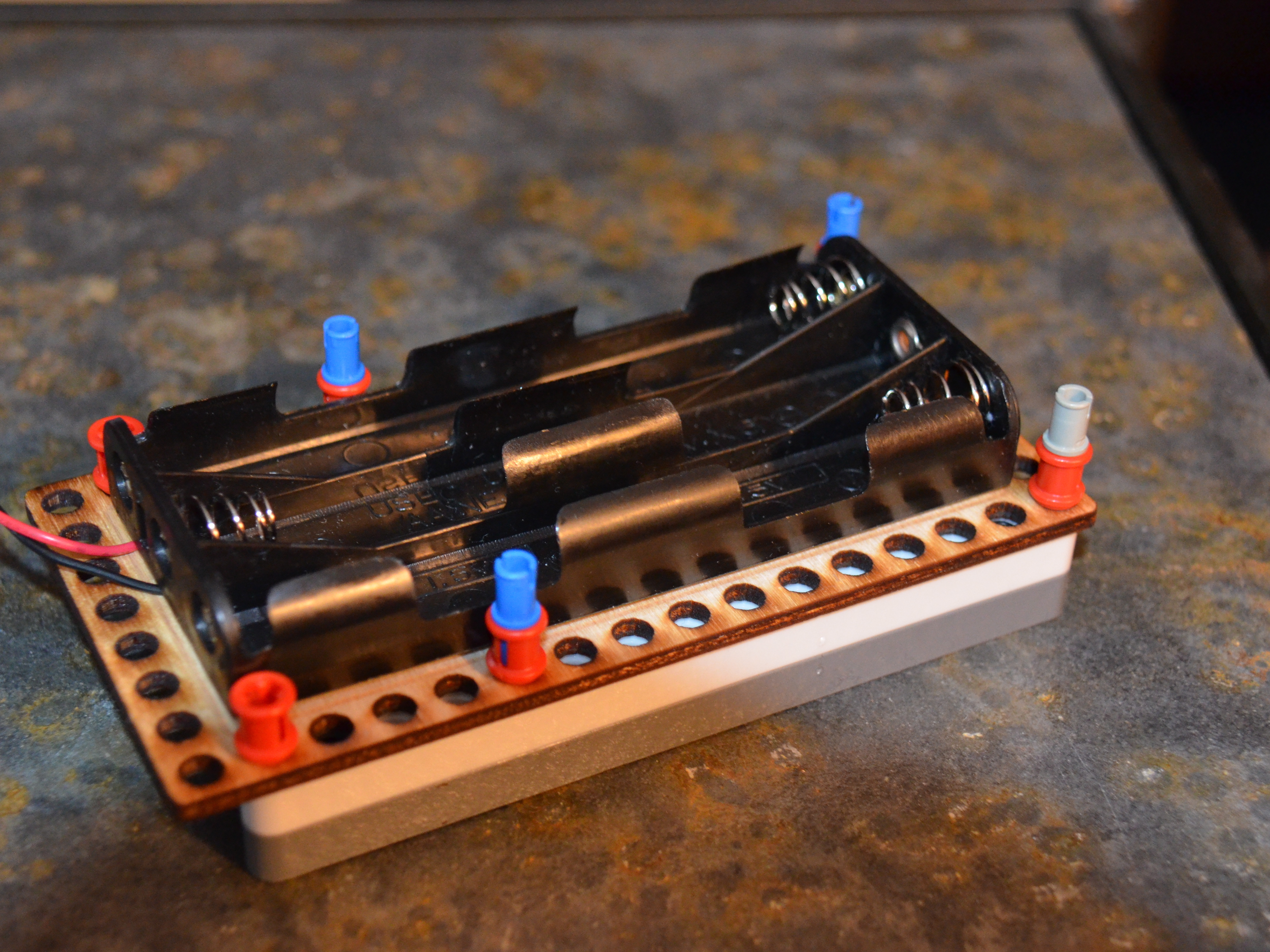
The guide that follows is a method for taking an extant adaptor board and taking step two; i.e., adapting the board to the design principles and function making it clean and functional.

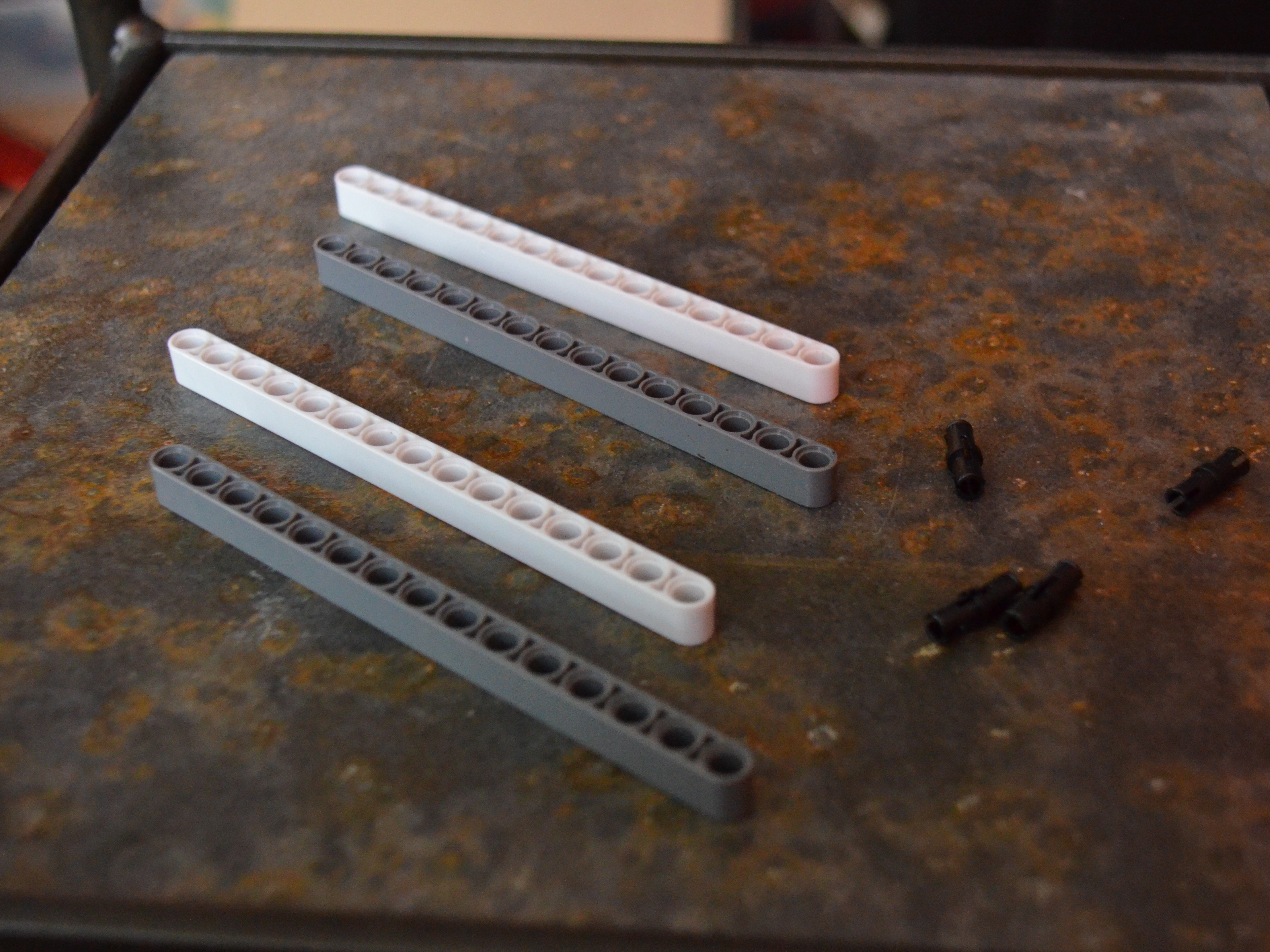
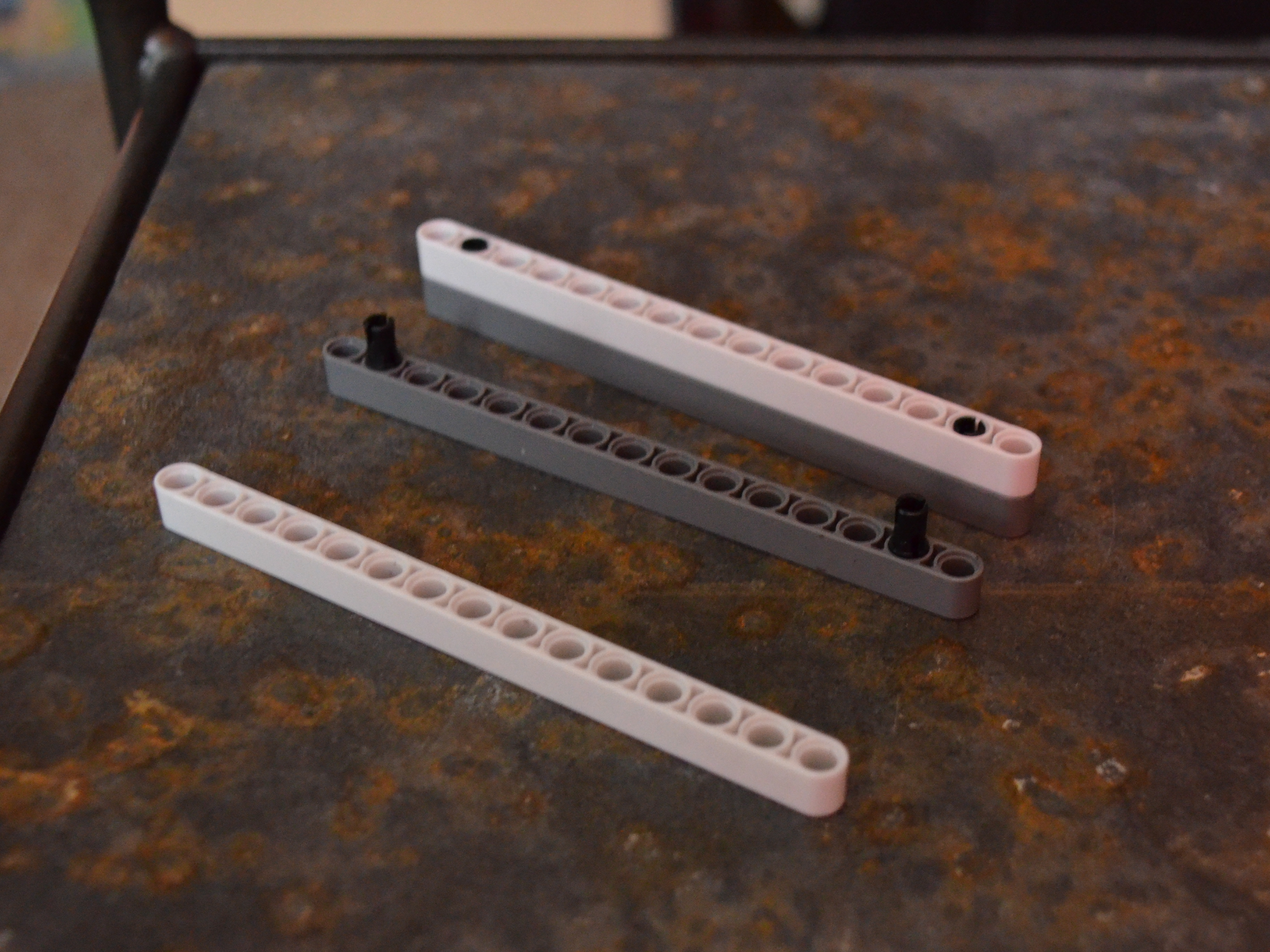
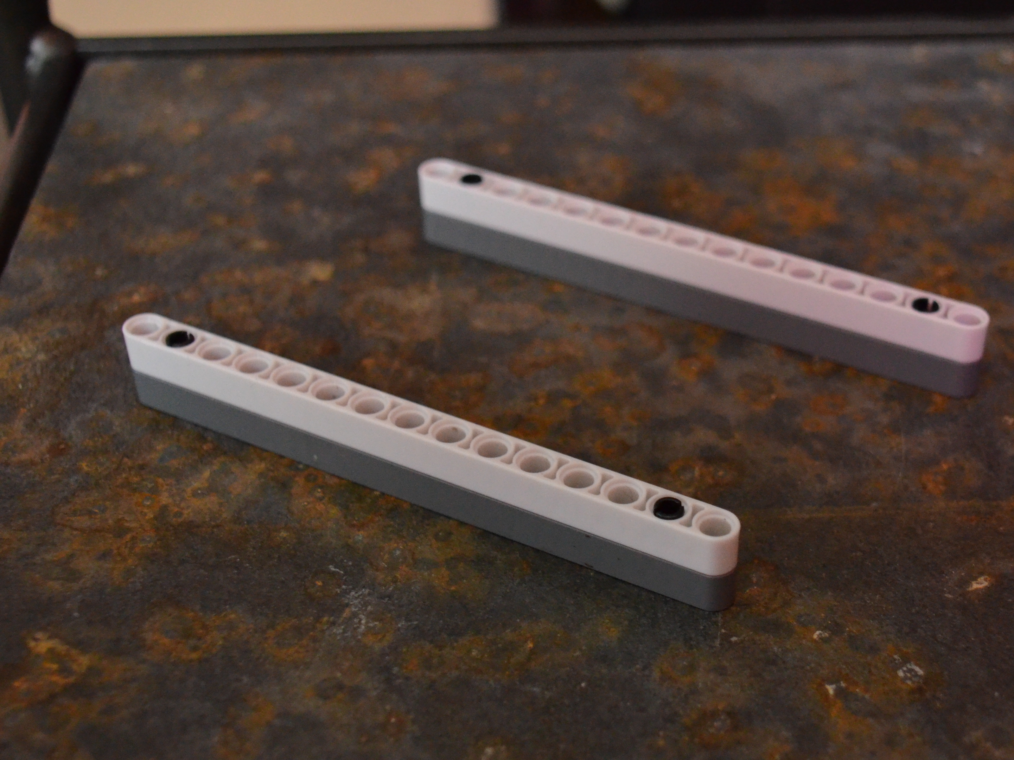
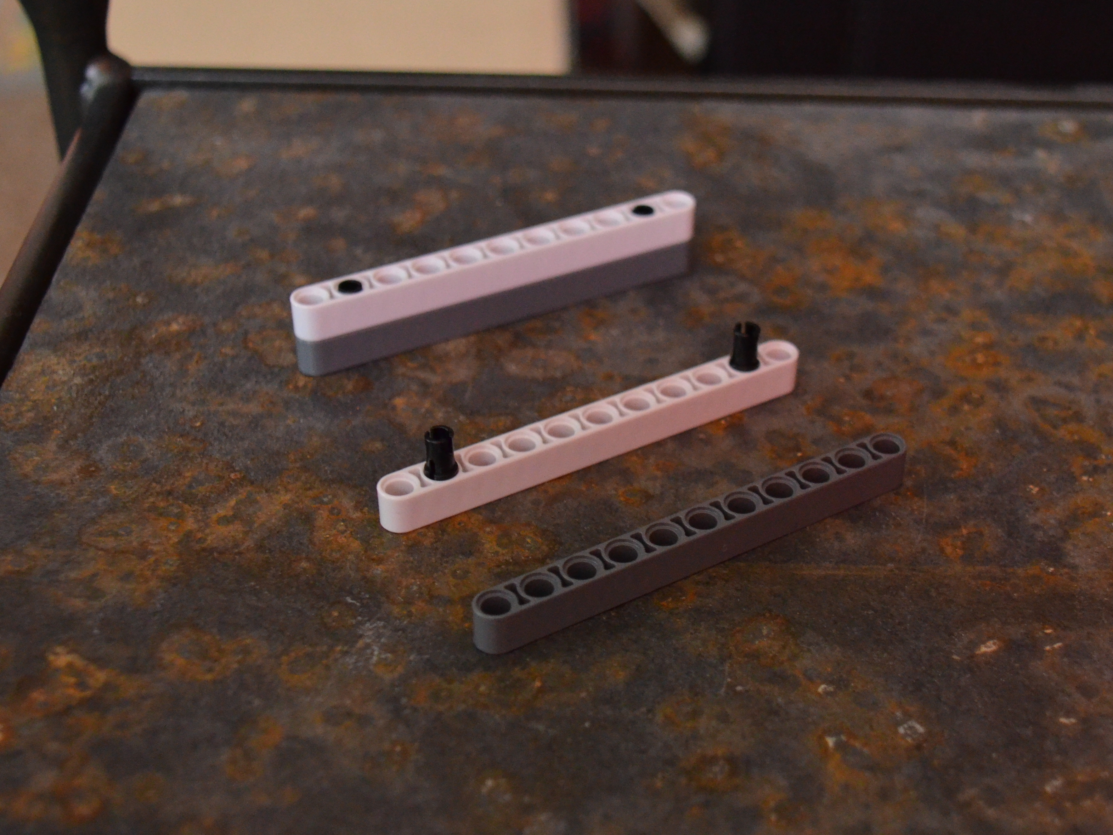
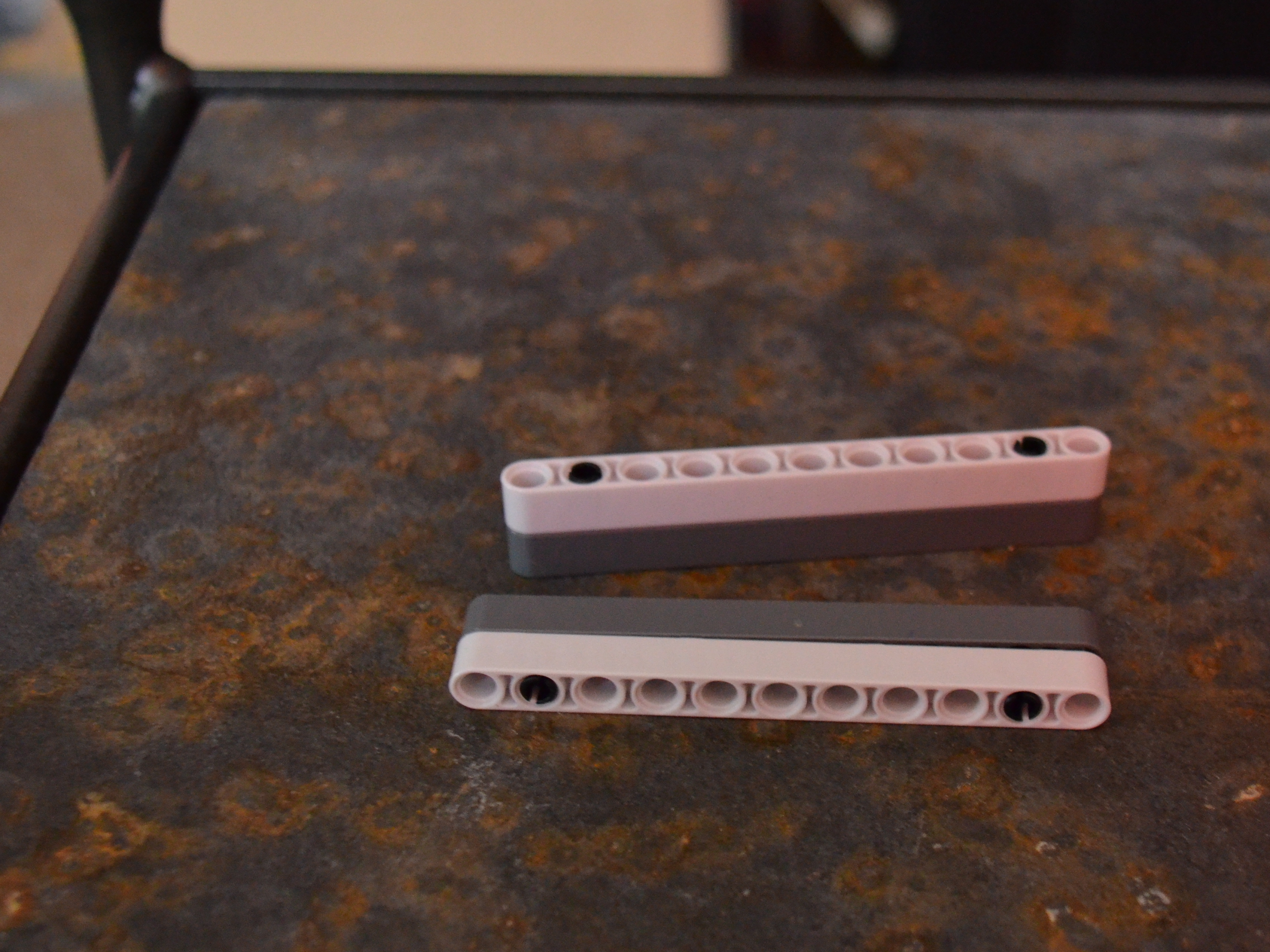
Though this design is specific to the boards that I link to in the parts section of the guide you can still glean some basic ideas from the guide such as offsetting to allow for space, pin placement techniques, and simplicity in design — these are universal to a good construction.

Project Steps

Attach Arduino and battery holder to the mounting boards.

Since I assume you already have these pieces I will leave it up to you to figure out the necessary screw and nut size.

Note: There is no need to cut down the screws. The design you are building will accommodate their length.

Take two 15M beams and connect them with two Connector Pins with Ridges (a.k.a friction pins).

Offset the pins’ placement one hole from the end of the beam on either side.

Repeat this step so that you have two of these beams.

Gather the Battery Mounting Board and six of the Friction Snap with Cross Hole.

Orient your mounting board so that the short side is facing you.

Drop the pins into the two corners closest to you — one in each hole.

Count up the long side of the board nine holes and drop in another pin. Make sure there are nine holes between the pin in the corner and the pin you just dropped in.

Count three more holes and drop a pin in. Note this pin is one hole from the corner.

Take the beams you made in Step One and the pins that you have placed through the holes in the Battery Mounting Board from Step Two and connect.

Your Battery Mounting Board is now secure between the pins’ female adaptors and the beams.

Make sure you connect the beams so that each of the end holes has a pin running through it.

Grab two 11M beams and two friction pins.

Connect the two beams together using the second hole from the end of the beam.

Repeat this step.

Round up eight pins with cross axles.

Four of the pins will attach via the cross axle side in to the female pins that protrude on the battery mounting board.

The other four pins will attach to the two beams just built at the end holes and with cross axles up.

Attach the pins protruding from the battery mounting board to the two 11M beams.

Make sure the cross axle pins on the 11M beams are at the top of the structure.

Finally, take your Arduino mounting board and slip it onto the beams and pins on the Battery Mounting Board.

You could just rest the Arduino board on these pins, but since you used cross axle pins you might as well use a full or half bushing to lock down your Arduino.

Conclusion

The LEGO parts can all be found in the NXT 2.0 kit or you can even substitute your own similar parts. This guide is as much a design experiment as it is a rote for execution.

I have not included the optional parts necessary for securing the final level of the adaptor; however, any LEGO Technic bushing or half bushing will do — you will need four of them.

The mounting boards need to be built or bought.