Anyone who’s shivered in the dark at a scary movie or laughed at the unintentional cheese-ball of a bad sci-fi (paging Ed Wood) knows the eerie sounds of the theremin. In the classic theremin design, two antennas control pitch and volume, and you play the instrument by moving your hands near the antennas without touching them.
This simpler design uses interrupted photons (light) instead of radio waves, and can be built with a handful of common components, including the versatile 555 timer chip. When we’re done, we’ll have a decent sounding mini-theremin. You can experiment with its sound by changing the type of light sensor used and the capacitance of the circuit.
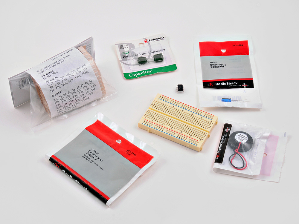
Gather together the breadboard, capacitors, speaker, resistors and photoresistor (or photodiodes).
TIP: I nearly always buy the large multi-packs of resistors; it saves time and money in the long run.
The schematic I based this project on called for a 0.47μF capacitor. I didn’t have any, so I used two 0.22μF capacitors in parallel. The values add, giving 0.44μF — and that’s close enough!
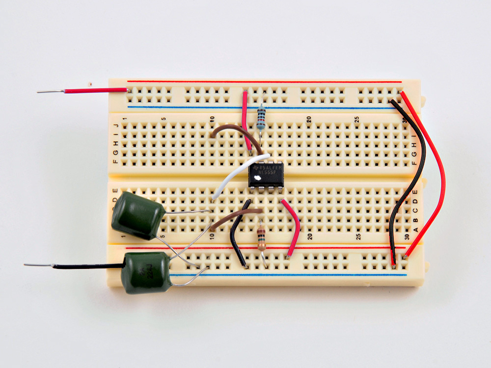
We are going to be building a 555 timer-based “astable oscillator circuit.” It sounds complicated, but really, it’s not that hard.
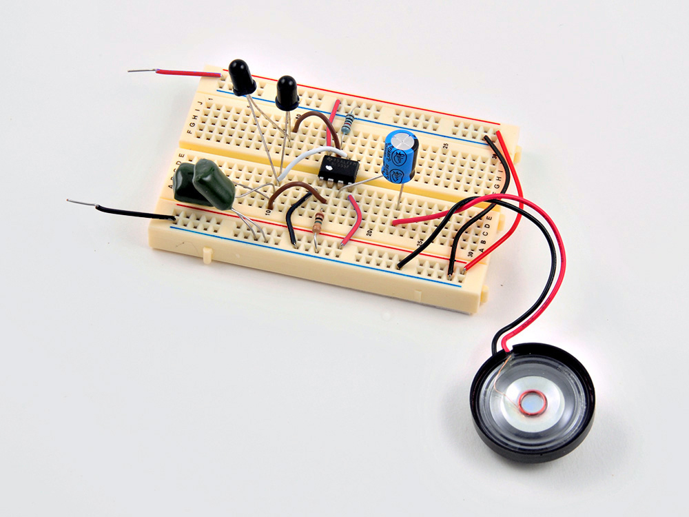
Our first task is to place the 555 timer IC on the breadboard. Note the location of the small dot indentation (which I painted white to make it more visible). That dot always marks Pin 1 on a chip.
I also added the basic power lines — red is +6v, and black is 0v (Gnd).
The two red wires carry the power lines between the top and bottom horizontal power “rails” on the breadboard.
Note: Electrolytic capacitors are polarity-sensitive. They can only safely go in one way. Note the orientation of the black band; it marks the negative lead.
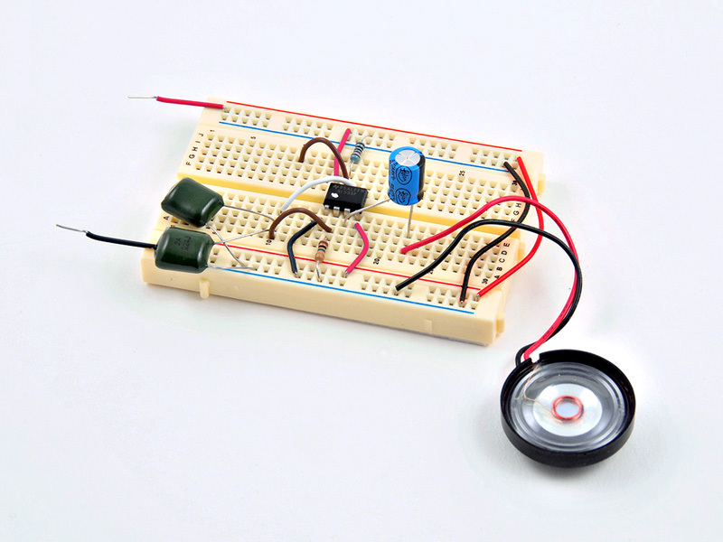
Add the speaker. Note the orientation of the red (+) and black (-) wires; it also needs to be connected with the correct polarity.
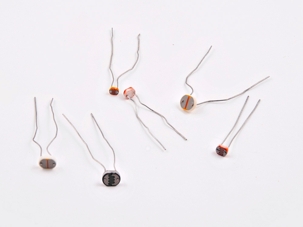
Install the two photodiodes (second image).
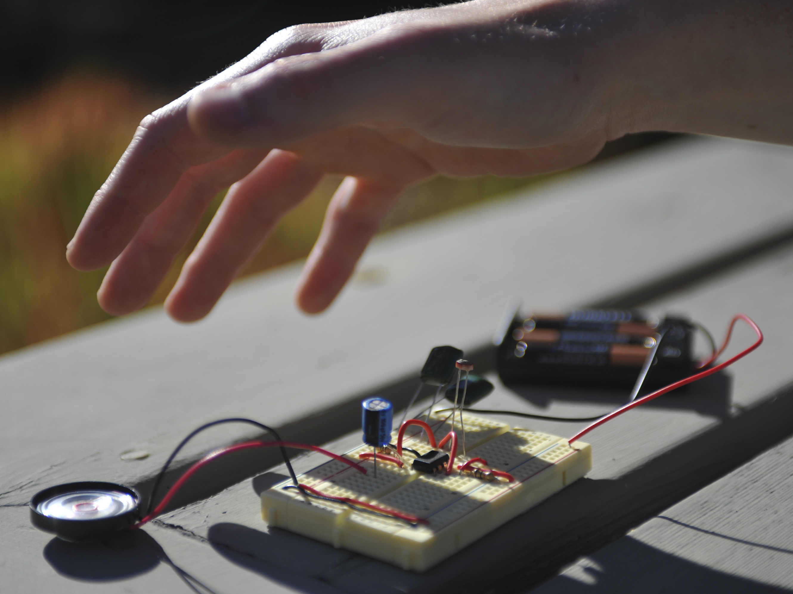
You should now be able to power up the device and hear a buzzing tone coming from the speaker. Move your fingers towards the photodiodes, and the pitch should go down.
That’s it! Move your fingers around the photodiodes to create different notes and sound effects.
Photodiodes work in this circuit, but you can get a broader range of tones by swapping in photoresistors, which RadioShack sells in a 5-pack.
Try different types of photoresisor, and also try removing one of the 0.22μF capacitors — this will alter the range of pitches you can produce.
See and hear the Light Theremin in action here and here.
Conclusion
The venerable 555 timer integrated circuit used in this project is the most popular IC of all time. You can learn more about it here and read about a chance encounter with the designer of the chip, Hans Carmenzind, on MAKE.
Our websites use cookies to improve your browsing experience. Some of these are essential for the basic functionalities of our websites. In addition, we use third-party cookies to help us analyze and understand usage. These will be stored in your browser only with your consent and you have the option to opt-out. Your choice here will be recorded for all Make.co Websites.
Allow Non-Necessary Cookies
Escape to an island of imagination + innovation as Maker Faire Bay Area returns for its 15th iteration!
Buy Tickets today! SAVE 15% and lock-in your preferred date(s).