01_pr_opener_01

This tutorial is from MAKE Vol. 1. 

The two key parts of soldering are good heat distribution and cleanliness of the soldering surface and component. With practice, you’ll become comfortable and experienced with the process.

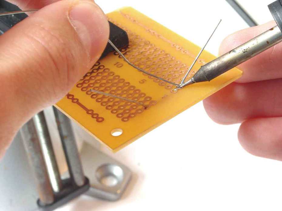
In this primer, I’ll explain how to solder a component onto a printed circuit board. I’ll also provide desoldering tips and show you how to remove a surface-mount component from a printed circuit board using a Chip Quik kit. And I’ll show you how to remove a component by removing the solder in a way that won’t damage the components or the circuit board.

Tools of the Trade

  • Soldering Iron: You could pay as little as $10 or as much as $1,000 for a soldering iron. I recommend a fine-tip, 700 degree F, 50W soldering stick iron. A good general-purpose iron for hardware hacking is the Weller W60P Controlled-Output Soldering Iron, which sells for under $70.
  • Solder: Should be thin gauge (0.032″ or 0.025″ diameter) 60/40 rosin core.
  • Desoldering Tool (AKA Solder Sucker): A manual vacuum device that pulls up hot solder, useful for removing components from circuit boards. I like the one RadioShack sells (#64-2098, $6.99).
  • IC Extraction Tool: Helps lift integrated circuits from the board during removal/desoldering.
  • Chip Quik SMD Removal Kit: Allows you to remove surface mount components quickly and easily. Visit www.chipquik.com for links to distributors. The kit is available for about $20.
  • Sandpaper: A very fine-grit sandpaper is useful for removing oxidation from component and circuit board surfaces.
  • Desoldering Braid: Woven metal material used to wick up melted solder.
  • Small, Flat-Tip Screwdriver: Comes in handy for removing some types of components.
  • Needle-Nose Pliers, Wire-Cutters, and Vise: These common tools will make your job easier.

Project Steps

Soldering a resistor to a circuit board.

This simple example shows the step-by-step processto solder a through-hole component to a printed circuit board (PCB). I used

a piece of prototype PCB and a single resistor.

BEFORE YOU START: Inspect the leads or pins for oxidation. If the metal surface is dull, sand with fine sandpaper until shiny. In addition, use the sandpaper to clean the oxidation and excess solder from the soldering iron tip to ensure maximum heat transfer.

Bend and insert the component leads into the desired holes on the printed circuit board (PCB). Flip the board to the other side. Slightly bend the lead you will be soldering to prevent the component from falling out when the board is turned upside down.

DANGER: It’s important to consider safety precautions. Improper handling of the soldering iron can lead to burns or other physical injuries. Wear safety goggles and other protective clothing when working with solder tools. With temperatures hovering around 700 degrees F, the tip of the soldering iron, molten solder, and flux can quickly sear through clothing and skin. Keep all soldering equipment away from flammable materials and objects. Be sure to turn off the iron when it is not in use and store it properly in its stand.

To begin the actual soldering process, allow the tip of your iron to contact both the component lead and the pad on the circuit board for about one second before feeding solder to the connection. This will allow the surface to become hot enough for solder to flow smoothly.

Next, apply solder sparingly and hold the iron in place until solder has evenly coated the surface. Ensure that the solder flows all around the two pieces (component lead and PCB pad) that you are fastening together.

Do not put solder directly onto the hot iron tip before it has made contact with the lead or pad; doing so can cause a cold-solder joint (a common mistake that can prevent your hack from working properly). Soldering is a function of heat, and if the pieces are not heated uniformly, solder may not spread as desired. A cold-solder joint will loosen over time and can build up corrosion.

TIP: Every so often during any soldering process, use a wet sponge to lightly wipe the excess solder and burned flux from the tip of your soldering iron. This allows the tip to stay clean and heat properly. Proper maintenance of your soldering equipment will also increase its life span.

When it appears that the solder has flowed properly, remove the iron from the area and wait a few seconds for the solder to cool and harden.

Do not attempt to move the component during this time. The solder joint should appear smooth and shiny, resembling the image at right. If your solder joint has a dull finish, reheat the connection and add more solder.

Once the solder joint is in place, snip the lead to the desired length. Usually, you will simply cut the remaining portion of the lead that is not part of the actual solder joint. This prevents any risk of short circuits between leftover component leads on the board.

Here’s a completed soldering example.

Desoldering — SMD Removal with Chip Quik

Desoldering, or removing

a soldered component from a circuit board, is typically trickier than soldering, because you can easily damage the device, the circuit board, or surrounding components. For surface mount devices (SMDs) with more than a few pins, the easiest method to remove the part is the Chip Quik SMD Removal Kit, as shown in the following step-by-step example.

BEFORE YOU START Use a rubbing alcohol pad to remove any residue from the solder pads. Verify that the solder pads are clean and free of cuts or solder jumps before proceeding.

Please read through this example completely before attempting SMD removal on an actual device. When removing the device, be careful not to scratch or damage any of the surrounding components or pull up any PCB traces.

The Chip Quik SMD Removal Kit allows you to quickly and easily remove surface-mount components such as PLCC, SOIC, TSOP, QFP, and discrete packages. The primary component of the kit is a low-melting temperature solder (requiring less than 300 degrees F) that reduces the overall melting temperature of the solder on the SMD pads. Essentially, this enables you to just lift the part right off the PCB. The kit consists of:

Alcohol pads for cleaning the circuit board after device removal.

The special low-melting-temperature alloy.

Standard no-clean flux, and application syringe.

Once the flux is evenly spread over the pins of the target

device, the next step is to apply the special Chip Quik alloy to the device. This step is just like soldering: apply heat to the pins of the device and the alloy at the same time. The alloy has a melting point of approximately 300 degrees F, which is quite low. You should not have to heat the alloy with the soldering iron for very long before it begins to melt. The molten alloy should flow around and under the device pins.

Starting at one end of the device, simply heat and apply the

alloy. Repeat for the other side(s) of the device. The flux will help ensure a nice flow of the alloy onto the device pins. Make sure that the alloy has come in contact with every single pin by gently moving the soldering iron around the edges of the device. Avoid touching nearby components on the PCB with the soldering iron.

Now that the alloy has been properly applied to all pins of the device, it’s time to remove the device from the board.

After making sure that the alloy is still molten by reheating all of it with the soldering iron, gently slide the component off the board.

You can use a small, jeweler’s flat-tip screwdriver to help with the task. If the device is stuck, reheat the alloy and wiggle the part back and forth to help the alloy flow underneath the pads of the device and loosen the connections.

The final step in the desoldering process is to clean the circuit board. This step is important because it will remove any impurities left behind from the Chip Quik process and leave you ready for the next step in your hardware hack.

First, use the soldering iron to remove any stray alloy left on the device pads or anywhere else on the circuit board. Next, apply a thin, even layer of flux to all of the pads that the device was just soldered to. Use the included alcohol swab or a flux-remover spray to remove the flux and clean the area.

The desoldering process is now complete. The surface-mount device has been removed and the circuit board cleaned. If you intend to reuse the device you just removed, use the soldering iron to remove any stray alloy or solder left over on and in between the pins and ensure there are no solder bridges between pins. If you do not want to reuse the device, simply throw it away.

DESOLDERING TIPS: For standard through-hole components, first grasp the component with a pair of needle-nose pliers. Heat the pad beneath the lead you intend to extract and pull gently. The lead should come out. Repeat for the other lead. If solder fills in behind the lead as you extract it, use a spring-loaded solder sucker to remove the excess solder.

For through-hole ICs or multi-pin parts, use a solder sucker or desoldering braid to remove excess from the hole before attempting to extract the part. You can use a small, flat-tip screwdriver or IC extraction tool to help loosen the device from the holes. Be careful to not overheat components, since they can become damaged and may fail during operation.

Conclusion

This project first appeared in MAKE Volume 01, page 162.