solar-panel-34_r

The sun is a renewable energy source that’s free and plentiful. Some people power their entire home with solar energy. A few even sell back the energy to the electricity grid for a profit.

I decided to start small and build my own solar panels to supplement my workshop power needs. Here, I’ll explain in detail how to build a 16.5-volt, 20-watt solar panel.


In the next volume of Make:, I’ll show you how to integrate the solar panel(s) into your electrical system.

Project Steps

Build the plastic case

To start, cut the acrylic to the following sizes:

  • 2 sheets 18″×24″
  • 2 pieces 1″×16″
  • 2 pieces 1″×24″
  • 2 pieces 1″×10″

If you purchased the acrylic from McMaster-Carr,
it comes in 24″×24″ sheets; you’ll need 2 of them to make all the parts. You can cut them with a jigsaw, but I recommend that you have your local glass company do all your custom cutting. Acrylic is difficult to cut because you have to use the right blade, and cut at the right speed. Many people end up cutting too fast; this results in the acrylic melting and then binding back to itself after the blade has passed.

An alternative is to cut the acrylic with a special acrylic cutting hand blade, which is good for acrylic ⅛” thick or less, but very difficult on our ¼” thick sheets. The method is to score the acrylic on the desired cut line multiple times, then place the sheet on the edge of a solid surface and press down to snap the section off from the rest of the sheet. It’s easier if the score line is farther away from the edge, so that you have more room to press down to snap the sheet.

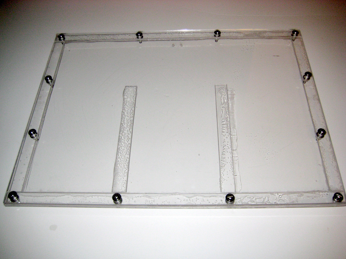
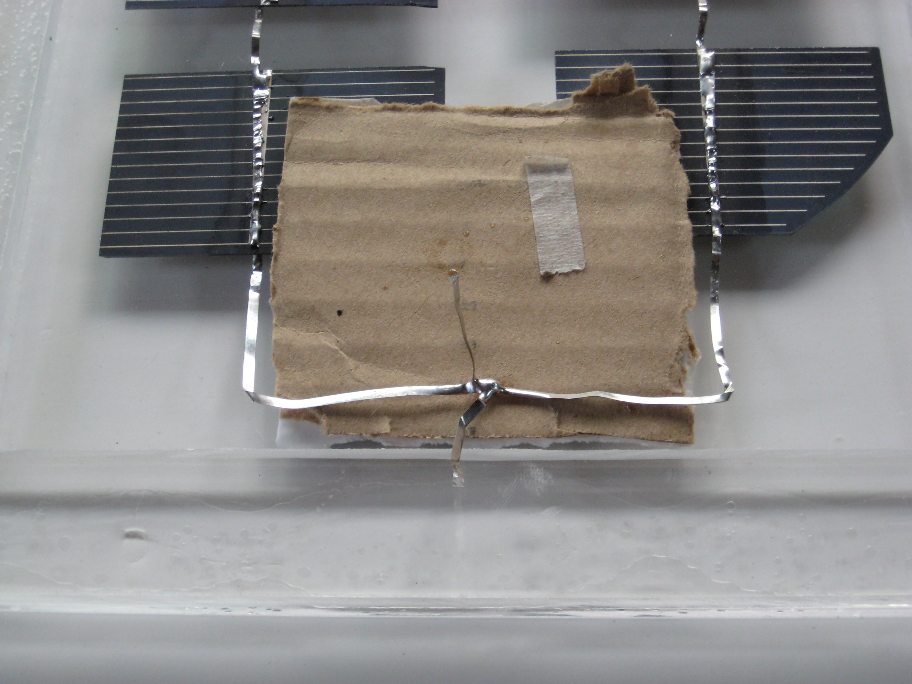
Peel the protective cover off one side of one 18″×24″ sheet. On this exposed side, fit together the two 1″×24″ pieces and the two 1″×16″ acrylic pieces to build a border, and then use the Duco cement to bond the border onto the sheet. Space the two 1″×10″ acrylic pieces evenly across the case, along the bottom 24″ border; I spaced them 6⅝” apart from each other. Note their position, and then use the Duco cement to bond them to the sheet. Let the cement dry according to the directions on the tube.

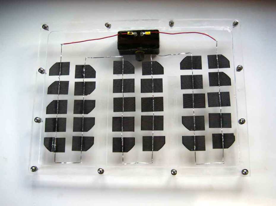
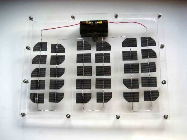
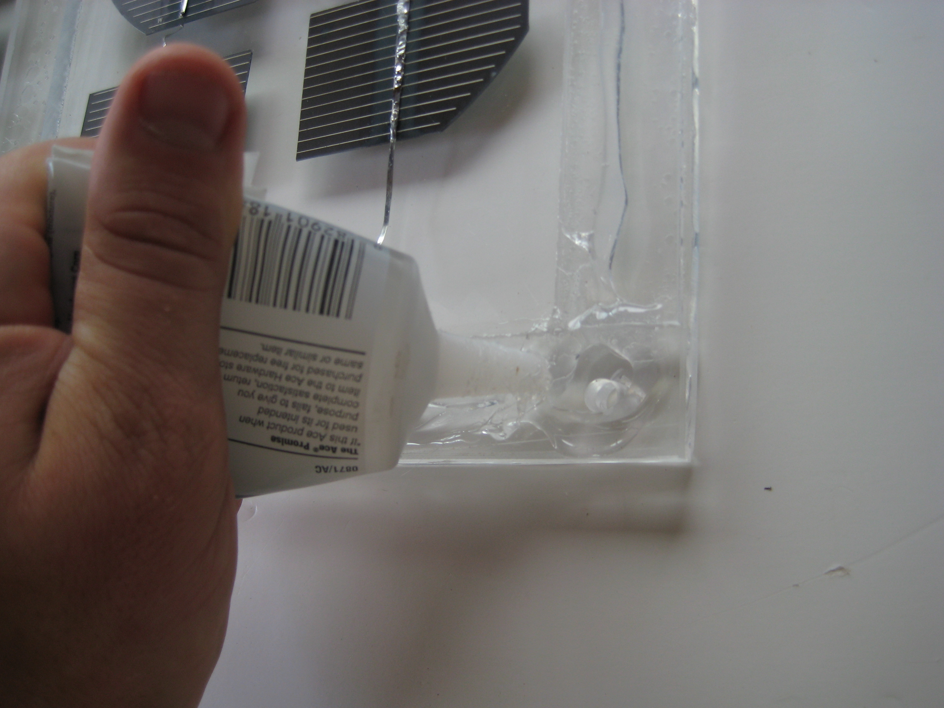
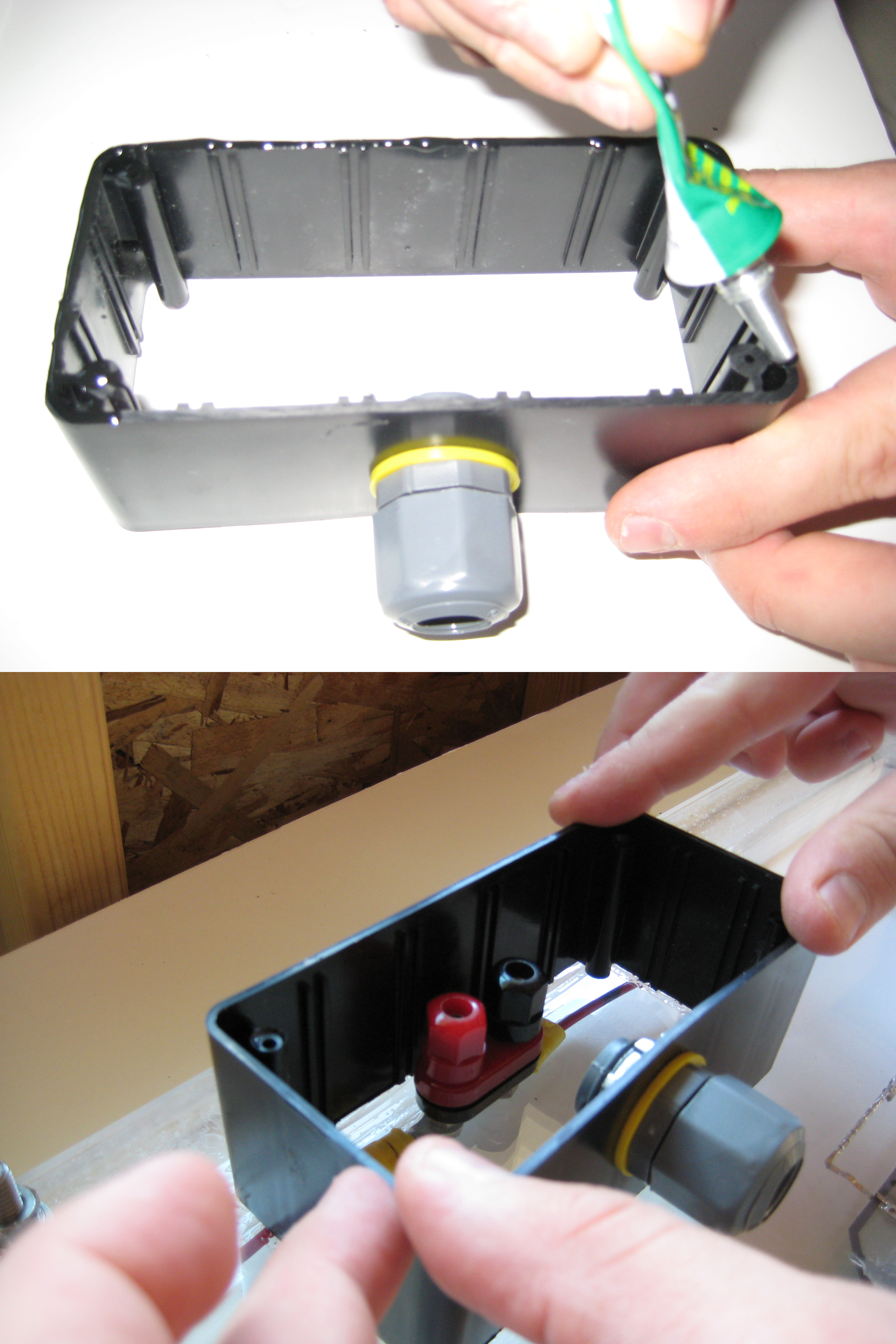
The dual binding post comes with a mounting template on the back of the package. Cut out this template and use it to mark the 2 drill holes on the acrylic sheet, ¾” apart and ½” from the top border edge (see second image for placement). Then use an 11/64″ or 3/16″ drill bit to drill both holes through the acrylic sheet. Insert the binding posts from the back of the acrylic sheet, then tighten the nuts on the binding posts on the inside of the case. You’ll have to clip off the tops of the binding posts to close the case with the top acrylic sheet.

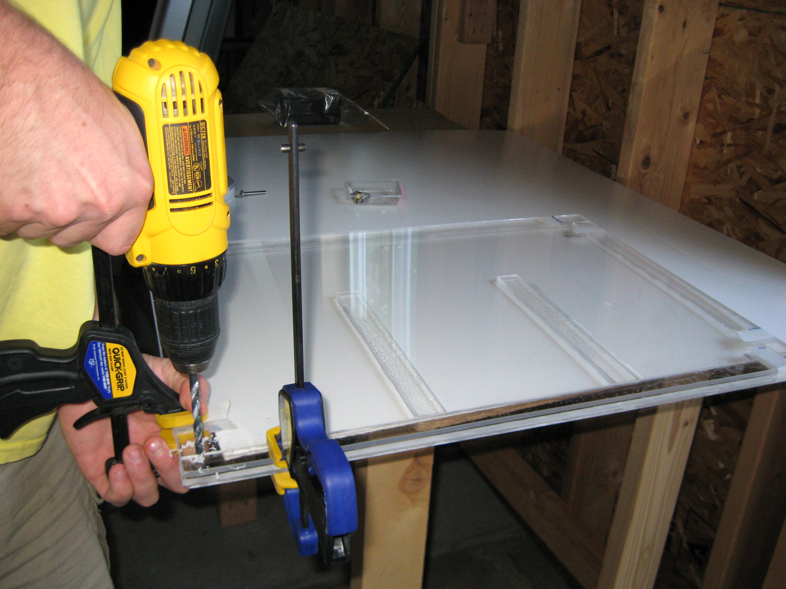
Place the second 18″×24″ acrylic sheet on top of the case, lined up with the edges of the other acrylic pieces. Tape this top sheet down to keep it from moving, and then clamp the whole case with at least 2 one-handed bar clamps to keep it steady during the drilling process.

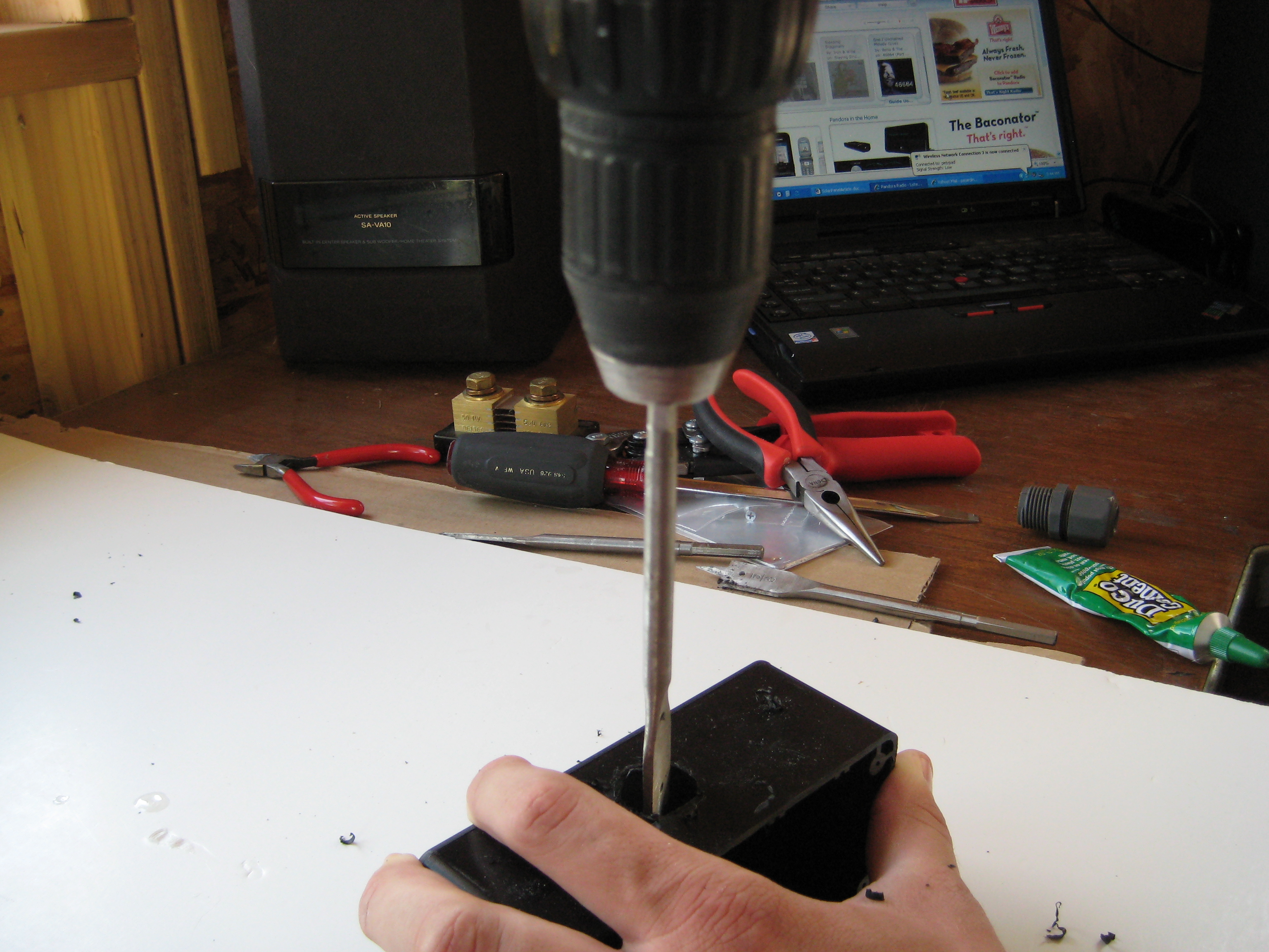
Using a ¼” drill bit, drill holes through the case border in 12 evenly spaced locations. After each hole is drilled, add its stainless hardware. This ensures that the case will line up evenly when you’re done drilling it. You don’t want the top sheet to shift at all during this process.

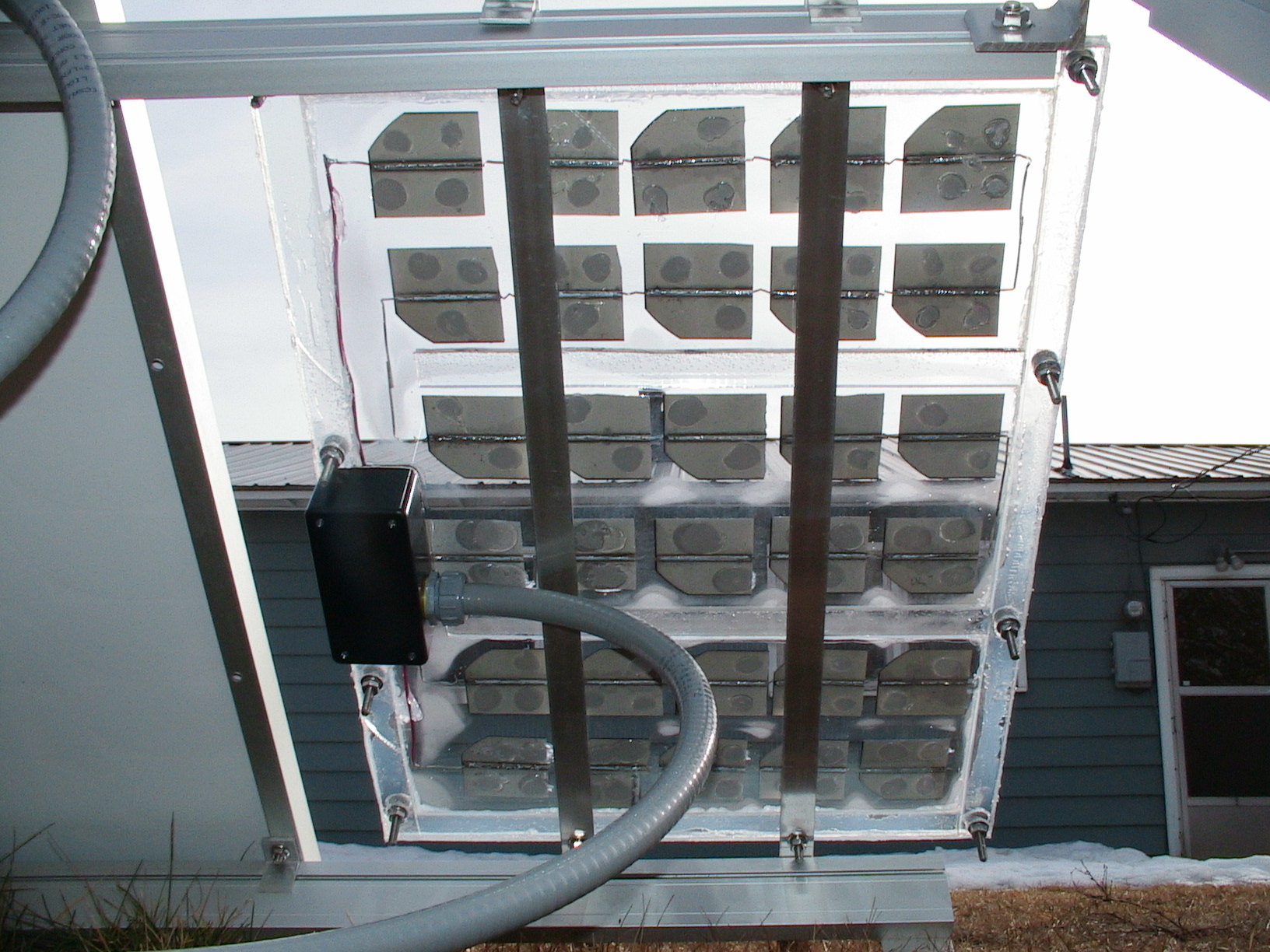
I also recommend that you start in one corner, and next drill the opposite corner. After hardware has been placed in each corner, I then drill 2 more holes along each side. This leaves a total of 12 bolts in the case. I do this to guarantee that the case won’t leak between the top sheet and the middle border. Congratulations, you now have a waterproof plastic case!

Solder the solar cells

If you haven’t soldered solar cells before, I recommend you try soldering cells that are considered scrap. You can buy scrap solar cells, by the ounce or by the watt, at siliconsolar.com. To brush up on your soldering skills, see the Make Video Podcast soldering tutorial here.

Cell Alignment and Tab Ribbon Length
Line up the 30 solar cells in 6 columns of 5 cells each on top of cardboard or fiberboard (first image). Arrange the cells in your desired layout. Measure the distance from the top edge of one cell to the bottom edge of the cell directly below it in the same column. You’ll cut the ribbon wire this distance plus ½”. After cutting the tab ribbons, bend each ribbon in the center to provide flexibility between each cell.

Tinning the Tab Ribbons
Tinning is a process where you apply solder to the length of the tab ribbon. This is a crucial step in the soldering process. Simply take the tab ribbon, and clamp one end in the helping hands tool. Heat up your solder gun and apply solder onto the topside of the tab ribbon. Apply only a small amount of solder, and try not to glob it on. Make sure you tin the appropriate edge of all tab ribbons before trying to solder the ribbon to the cell (second image).

Solder the solar cells (cont'd)

Preparing the Solar Cells
Apply a small amount of flux to the surface of the solar cell where you’ll solder the tab ribbon. Make sure to wipe off excess flux, because too much flux can prevent your tab ribbon/solder from bonding to the solar cell. It will also decrease the efficiency of the cell if a layer of dried flux is blocking the sun. Some soldering experts say it’s a good idea to scuff up the area where you plan to solder; this scuffed-up surface may make it easier for the tab ribbon and solder to bond to the cell.

Connecting the Rows
When assembling each row of 5 cells, make sure you solder the bottom or top cell with a longer piece of tab ribbon. This ensures that the row can connect to its adjacent row without adding more than one solder joint.
NOTE: Wait until all rows are soldered and placed permanently in the case with the RTV silicone before soldering the connections between rows.

Start by soldering the tinned edge of a tab ribbon to the topside (shiny side) of the first solar cell. Lay a tab ribbon halfway up the cell, with most of its length extending up beyond the edge of the cell. Make sure to solder the entire length of the tab ribbon. Now solder the second, third, fourth, and fifth solar cells exactly like the first one (third image).

Solder the solar cells (cont'd)

Next, flip over the 5 solar cells. The tab ribbon that extends above one cell will now be soldered to the backside of another cell. Solder all 5 solar cells together connecting each topside to the backside
of the next cell.

Verify that you soldered the cells together correctly, by using the voltmeter to test the positive and negative ends of the newly soldered row of solar cells. Face the topside of the cells into the light and test the voltage. The voltage should be approximately 2.5V (the actual voltage will be slightly higher). Be sure to test the voltage of each row of soldered cells (third image).

Solder the solar cells (cont'd)

Now that you’ve connected 5 cells to form
1 row (Figure A), copy this exact process for 2 more rows, using a total of 10 more cells. Place the 3 newly soldered rows on the left side of each section inside the case (Figure B).

Solder 3 more rows in the same manner as the first 3; these will be the right-hand rows. Now rotate them 180 degrees, so their voltage runs opposite to the left-hand rows. You’ll solder the ribbon wire from each left-hand bottom cell (positive voltage) onto the top (negative) side of each right-hand bottom cell (Figure C), and you’ll turn the corner at the tops of the rows in a similar way (Figure D) — but don’t solder yet. First, place all 3 right-hand rows in the plastic case and verify their position in relation to the other cells (Figures E and F).

Install the cells and wire the case

After all the rows have been set into the case, apply RTV silicone adhesive to the back of each cell. I usually apply a generous amount in 2 or 3 spots. Be careful not to crack or break the cells. After applying the silicone, place the row into the case at the desired location. After the silicone has dried, the cell cannot be removed from the case.

After all the rows have been glued into the case, solder the connection between each row. Use a piece of cardboard to keep from damaging the acrylic with the solder tip.

Cut 2 hookup wires to length, extending from the end of the positive and negative tab wires to the binding posts. Crimp a ring tongue terminal to each wire, solder the opposite end to the tab ribbon, and then tighten the terminals onto the binding posts. Apply some RTV silicone to the hookup wire, so it won’t move around in the case. You can also just use more tab ribbon instead of the hookup wire to connect the solar cells to the binding posts (Figure F from Step 5).

Before sealing the case, test both the positive and negative binding posts in the sun to verify that you have the appropriate voltage. The voltage should be approximately 16.5V.

Seal the case

Apply a generous amount of silicone sealant all the way around the border of the case. Make sure you apply it around the holes where the stainless steel hardware will hold the case closed.

Place the top acrylic piece on the top of the border to seal in the cells. Now fasten the stainless steel hardware to the case.

Install the junction box

First, cut off the closed end of the project enclosure case. Make sure you cut it straight. You can use a jigsaw, table saw, miter saw, or handsaw. Drill a ¾” hole into the side of the project case.

The ¾” hole in the junction box is for the ½” watertight compression wire connector. This
connector can be used with 14/2 or 12/2 outdoor-rated wire, or flexible conduit as seen in the second image.

Many watertight connection options are available, including metal conduit.

This solar panel does not include a diode to protect the panel from reverse current. If you’re not using a charge controller between your batteries, you’ll need to add a blocking diode to your solar panel. This prevents reverse current flow back to the panel at night.

Install the junction box (cont'd)

Place the project box over the exposed binding posts on the back of the solar panel. Note your desired position, apply a generous amount of Duco cement to the cut edge of the project box, and then place the box in position. Let the cement dry for a few hours, then apply a generous amount of silicone sealant around the edge of the box, inside and outside, to ensure a watertight seal). Your charger is built (third image). Now it’s time to put it to work.

Conclusion

Mounting and Grounding

Mounting Options

I recommend mounting solar panels onto 2 aluminum rails. Place the aluminum rail against the stainless steel bolts, hammer the rail, then flip the rail over; you’ll now see the drill locations needed.

I’ve also used UniRac’s SolarMount modular mounting system; I purchased 2 rails and 2 tilted legs to create a ground mount system that can also be used on a flat roof. Drill holes in the rails to match the mount on the UniRac mount system.

picture


Orientation

It’s recommended to orient solar panels toward due south. Simple enough. You also want to angle your solar panel perpendicular to the sun. However, the sun follows the azimuth angle throughout the day — the greatest charging potential is during solar noon — and the sun’s angle changes not only throughout the day, but also throughout the year.

If you’re going to mount the solar panel in a fixed position, a good rule of thumb is as follows. If you are off-grid, mount the solar panel for latitude plus 15 degrees. Winter is the season that’s most critical for off-grid homes, because of the lack of sunlight.

If you have a grid-tie setup, mount the solar panels for latitude minus 15 degrees. This orientation will increase your generation during summer months, when you can sell more power back to the grid, or use it for air conditioning.

If your solar mounting system is adjustable, adjust the panels at least 4 times a year, bringing them (roughly) perpendicular to the sun angle at solar noon. Go here to see tools related to the solar path for your particular latitude.

Grounding

According to the National Electrical Code, all solar panel systems need to be grounded to code. I recommend reading the NEC handbook for detailed information regarding electrical codes. At a minimum, the NEC requires that all systems must have equipment-grounding conductors that connect the metal surfaces of the solar panels to a ground rod. My grounding system consists of the following items:
  • Two code-compliant ground lugs screwed into each aluminum rail that touches the solar panel.
  • An 8-foot grounding rod driven into the earth near the solar panel array.
  • 6-gauge stranded copper wire (preferred) or solid wire connected to the ground lug and then to the ground rod.
Also read John Wiles’ article, “To Ground or Not To Ground: That Is Not the Question (in the USA),” available here.

picture


System Design

In the next volume of MAKE, I’ll show you how to connect the solar panel to your electrical system. For now, check out the image above for a visual overview of the electron flow in a typical solar system.