YouTube player

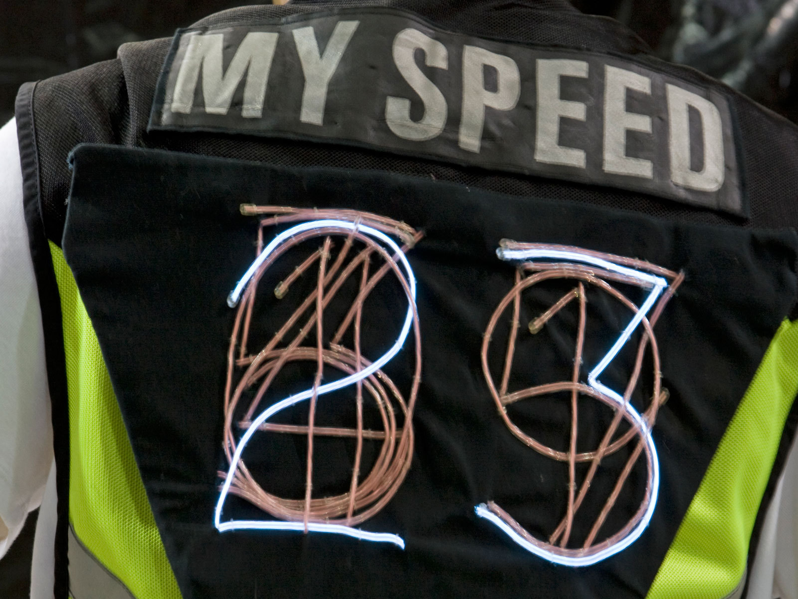
This lightweight night-cycling vest displays your current speed in glowing, 7-inch-tall numbers easily visible to cars. On the back, an Arduino microcontroller reads input from an off-the-shelf bike speedometer sensor, and then switches power to sewn-in numerals made from electroluminescent (EL) wire.

Bicyclists receive a lot of honk-based grief from car drivers who perceive them as slow and in the way, and when drivers misjudge a bicycle’s speed, it can cause “right hook” collisions that kill several bicyclists each year. If car users knew how fast cyclists were moving, would they be more willing to share the road? What if a bicycle prominently displayed its speed to the cars behind it, using large, brightly lit digits?

Brady Clark, cycling advocate and design genius, asked me to help him answer this question. At first I assumed it was beyond me, since I was a software guy who barely understood electronics. But I love to learn, and the Dorkbot community in Portland, Ore., was encouraging and helpful.

Our final motivation was the Bike Gadget Contest in Minneapolis, sponsored by the Bell Museum and The Hub, a bike co-op. After some research and shopping, we completed this project in a manic three-day push, then delivered it to the contest judges within minutes of the entry deadline.

Project Steps

Assemble the protoshield.

The ProtoShield lets you build circuits directly on top of the Arduino board. I assembled it following Atomicsalad’s excellent ProtoShield tutorial.

If you’re really in a hurry, you can leave out all the female headers. But if you might use your ProtoShield for other projects later, it’s better to assemble the whole thing (and you’ll still have to do a lot of desoldering.)

Build the control circuit.

For each display digit, an Arduino output pin connects through 1 resistor to 1 triac. The other 2 pins of the triac connect to ground and the digit’s ribbon cable pin. It’s a simple circuit; the tricky part is fitting 12 of them onto the ProtoShield. (There are too many connections to use the ProtoShield’s mini solderless breadboard.) Here’s how I did it. Refer to the schematic for all connections.

Plug the 2×7 male header across the middle of the board, perpendicular to the rails and with one end adjacent to the ground (GND) rail.

Plug in the 100Ω resistors just below the 5V rail in 2 rows of 6, grouped on either side of the male header. Underneath, connect one end of each to one of the D0–D13 contacts, on the female headers if present, or else on the board itself. Leave D3 empty for the speedo interrupt. To save room, orient the resistors vertically.

Arrange triacs at the intersection of each resistor and header pin. For each triac, the gate lead (pin 2, the middle pin) will connect through a resistor to one of the Arduino’s digital outputs D0–D13. This pin controls the flow between the other 2, like the base of a transistor. Pin 1 of the triac, on the left as you read the printing on its face, connects to ground, and pin 3 connects to the ribbon cable via the 2×7 male header.

On the underside of the board, connect the resistors, triacs, and ribbon cable header following the schematic. I simply bent and soldered down the uncut leads, rather than the usual method of trimming leads and connecting with insulated wire. Apologies to any professional electrical engineers who are nauseated by this.

Connect the speedometer sensor’s 2 wires to power (5V) and one of the Arduino’s interrupt pins, D2 or D3 (I used D3). Also tie that same pin to ground with the 1kΩ resistor; otherwise, your sensor might detect nonexistent ghost bikes in your vicinity. Different ProtoShields have different layouts, so you should make these connections wherever it makes sense for your board.

On the one shown here, made by MAKE intern Kris Magri, the speedo connects to one end of the 5V rail and an adjacent hole, which is wired up to D3 on the underside. The 1kΩ resistor fits into the row of 100Ω resistors and connects to ground.

On my v.1 ProtoShield, the power, ground, and D3 pins all sit on the BlueSMiRF header, so I plugged the speedo in there. This project doesn’t use Bluetooth, and the BlueSMiRF header was a handy place to connect.

Connect the EL wire power supply’s black wire to the board’s ground rail and its red wire to both adjacent pins at the end of the ribbon header, bridging the 3 pads underneath. This divides the power so that one ribbon wire feeds the left digit and the other feeds the right.

Use electrical tape to insulate all exposed conductors, and shrink any heat-shrink tubing you’ve applied.

Solder one lead from each digit (either lead) to individual wires of the ribbon cable. These are the grounds. You can be systematic and plan ahead which pin goes to which numeral, but we decided not to keep track and to make the associations later in the software.

Test the circuit.

Download and install the latest Arduino software from http://arduino.cc. On older versions of Mac OS X, you may also need to install the provided USB Serial Driver, so that your computer sees the Arduino as a serial port.

With the ProtoShield unplugged, hook the Arduino to your computer. Download and run the “Blink” example code, on the Arduino site under “Learning/Examples,” to prove that your whole toolchain works.

Download the test software Test_EL_Digits.pde. Plug the ProtoShield into the Arduino and the ribbon cable into the ProtoShield.

Run the test software, which cycles through each output pin in order, so you can spot any bad connections. Quality control and breakage can be an issue with EL wire, so handle it gently and make sure each segment works. One bad segment can short out the whole circuit, in which case you should check the resistance across all of them.

Build the display.

If you’re working with plain EL wire rather than prepared segments, you need to connect leads to the core and wrap wires of each piece. Cut the EL wire into 16″ segments, and burn off 1″ of the outer sleeve at one end to expose the wrap wires. Make 12 of these segments.

To make a solderable contact for the wrap wires, you can carefully tease them to one side and twist them together, or else belt them with a snug loop of copper tape. Then use a knife or stripper to remove the phosphor underneath and expose the core wire.

Split and strip a dozen 10″ leads, then solder the EL core and wrap wires to separate lead wires. Use heat-shrink tubing to insulate and reinforce the joints, remembering to slip the pieces over the leads before soldering.

Pin the cloth around a frame of plastic or cardboard, then run strands of EL wire along the path of each digit, entering and exiting through holes cut in the backing cloth at the bottom of each numeral.

To anchor the EL wire to the fabric, we used a great tool the CooLight folks hipped us to: the Buttoneer. It’s designed to attach buttons to clothes using small plastic staples, but it also works brilliantly for attaching EL wire.

EL wire can’t take sharp bends without breaking. To create the hard corners that discerning digit-users crave, run it out the back through a hole, loop it around underneath, and bring it back up at the different angle.

Once the digits are affixed, rip away the paper underneath, bit by bit.

Trim any excess EL wire off the digits. If you’re using precut segments, move the end caps onto the new ends; otherwise, cap the ends with a bit of heat-shrink.

For the other, non-ground leads, twist them together into a single mass on each side of the ribbon cable and solder them to the 2 pins that connect to the power supply.

Configure and run the software.

Download and run the Speed Vest software, speedo_4.pde, as in Step 5. When the program starts, it cycles through each output pin in order, so you can identify which pin feeds to which digit. At this point the numbers should light up in random order.

Unplug the ProtoShield and use a multimeter to probe and map the connections between the Arduino output pins and the digits. Then edit the array definitions for onesPins and tensPins at the top of speedo_4.pde to reflect the associations. Edit and rerun the software as needed until the numbers boot up in order.

Test the system on the bench by holding the 2 halves of the wheel sensor and brushing the magnet past the switch in a regular rhythm, to simulate the rotation of a wheel. At this point, we found it very gratifying to see our work light up!

Assemble the vest.

Now attach the hardware to the vest. We used velcro tape, but with hindsight I recommend you sew it or use plain old safety pins. They’re cheaper and more secure, and we haven’t yet needed to remove and reconnect the display.

(Optional) Brady used his beloved Print Gocco miniature screen-printing kit to add some extra safety-bling to the vest: a reflective “MY SPEED” banner to run along the top. You could also just use reflective paint or tape.

Oops! Quick — build a case! (duh!)

It’s stunningly un-chic to have dangly bits of electronics trailing out behind your butt, or tangled in your spokes. But somehow, we failed to foresee the obvious need for a case. Under extreme deadline pressure, our original Speed Vest had a ghetto-tech case made from scrap cardboard and rubber bands.

For the version shown here, built by Kris from MAKE, she used a plastic soap dish, and then after that disappeared from the lab, she tucked it into a small box. The case just fits into the pocket of the vest, so it isn’t visible, but I’ll still bet you can do better!

We ran the ribbon cable through a tiny slit in the integrated rear pouch of our vest. The case fits snugly in the pouch, hiding all our sloppiness while letting our invention shine!

Special thanks to Nick Sanders at West County Cycle Service for his help with our build.

Conclusion

The Display Mannequin

With less than 12 hours remaining before our all-motivating contest deadline, we began work on our floor display. We made a mannequin to wear the Speed Vest by casting Brady, using Mark Jenkins’ packing tape sculpture technique (http://tapesculpture.org). Add one bicycle and one bicycle work-stand, and we were ready to wow the public.

SpeedVest II

It’s hard to know just how car drivers feel about the Speed Vest, but so far nobody bicycling while wearing it has been honked at or run over. Meanwhile, we’re now working on SpeedVest II, with four major areas of improvement:

  • Wirelessness If the rider forgets he’s plugged into the bicycle when he dismounts, the electronics get yanked. In practice, this happens almost every time, and we’ve had to resolder the connectors three times already. SpeedVest II will use Zigbee wireless modules to transmit speed data from the wheel to the Arduino.
  • Size In bicycle equipment, lightness is everything. The Arduino USB board is handy, but contains a lot of parts we don’t use. With a custom PCB design, we can get the whole system much smaller and lighter.
  • Power The Arduino is powered by a 9V battery, but the EL wire inverter has its own AA battery and a separate power switch. The batteries run out at different times, and turning the unit on and off is a two-step process. Our improved single-board design will integrate the inverter, driven from the same power source as the rest of the board.
  • Speed range Bicycles are fast, and getting faster! Our vest displays speeds up to 69mph, but the current bicycle land speed record is 81mph. (And that’s not even close to the drafting speed record of 152mph, set by a bicyclist chasing a specially designed car that pushed away the forward wind resistance.) So we’re redesigning our numeric display to show all speeds from 1 to 99 miles per hour. We hope that will suffice for normal use.

The Contest

We handily accomplished our first mission: winning The Hub’s Bike Gadget Contest. W00t!

Then we set about testing the Speed Vest in real traffic. We’ve had great success with it, and the feedback from everyone who’s seen it has been wonderful. Many people want their own.

Also, simulating a wheel with your hands, and seeing how fast you can make the speed display go, has become a strangely compelling party game.

Resources

Download all project code, schematic diagrams, and templates at http://archive.makezine.com/19/speedvest.