


This project first appeared in MAKE Volume 38, on pages 94–95.
Robotics, manufacturing, intruder detection, and signaling. These are just a few of the applications for electronic circuits that detect the presence or absence of light. Dark-activated nightlights and street lamps are among the most common applications. So are infrared remote control receivers. A wide variety of semiconductor light sensors is readily available and you can quickly learn to use them by plugging simple circuits into a solderless breadboard.
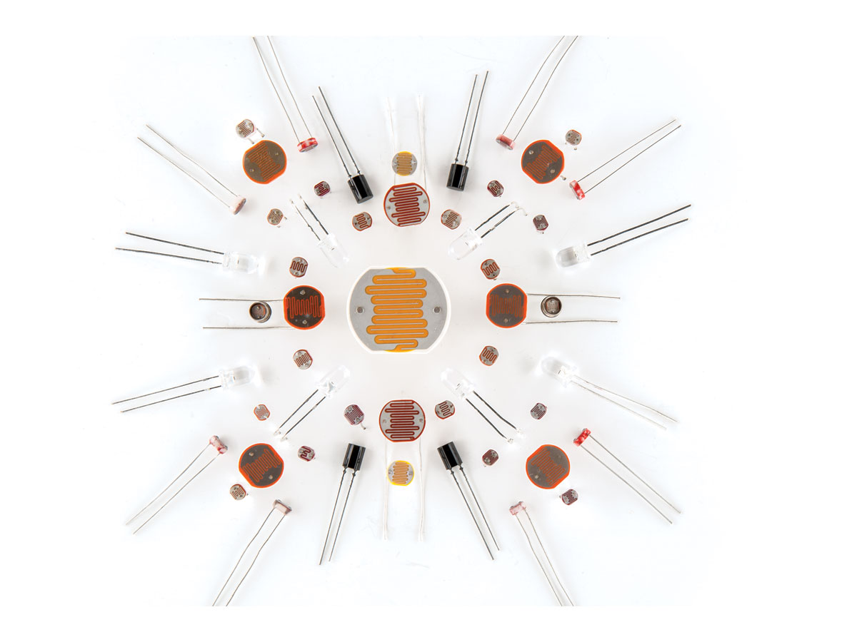
Photoresistors
Photoresistors, also known as photocells, are 2-lead devices with a light-sensitive film most commonly made from cadmium sulfide (CdS). When dark, photoresistors have a high resistance, which light greatly reduces.
You can connect an ohmmeter to a photoresistor to see how its resistance changes with light. Figure A shows how to convert changes in photoresistance into a voltage by means of simple voltage divider circuits. Both circuits use a potentiometer to calibrate the output voltage.

Photoresistors are inexpensive, and they can be connected in either direction without regard to polarity. These features make them among the easiest-to-use light-sensing components. Their main drawback is that they respond to light more slowly than other kinds of light sensors.
Most CdS photoresistors respond across the visible spectrum from around 400nm in the violet to 750nm in the near infrared while peaking in the green at around 550nm. This closely resembles the response of the human eye (400nm to 700nm).
While photoresistors are very popular, their days are numbered. In 2006, CdS photoresistors were banned in European Union countries by the Restriction of Hazardous Substances Directive (RoHS). The ban is because the light-sensitive film in these sensors contains a tiny amount of cadmium, which is toxic. CdS photoresistors are still widely available in the US.
Make an Ultra-Sensitive Photoresistor Light Sensor
A simple 555 integrated circuit pulse generator like the one in Figure B provides a good way to appreciate the high sensitivity of a CdS photoresistor. You can assemble this circuit on a solderless breadboard in a few minutes. Figure C shows the pin outline for the 555 IC.


Place the circuit at one side of a dark room with the CdS cell pointed toward the opposite side. Wait until the speaker emits a click every few seconds and walk to the opposite side of the room. When you point a flashlight toward the circuit, the resistance of the photoresistor will slightly decline. This will cause the interval between clicks from the speaker to become noticeably briefer. With slightly more light the clicks will merge into a buzz or tone. If the sound is too loud, increase C2 to 1µF or 10µF.
Make Photoresistor Dark and Light Sensors
Photoresistors are ideal sensors for nightlights. The left circuit in Figure D activates LED1 when light strikes a photoresistor; the right circuit switches off LED2 when the photoresistor is illuminated.

Phototransistors
Bipolar (NPN and PNP) transistors have 3 leads: the collector, base and emitter. A small signal at the base modulates a much larger current flowing between the collector and emitter. This is how a transistor amplifies a very small signal or functions as a switch.
In a phototransistor, light serves the same purpose as a signal applied to the base of an ordinary transistor. Some phototransistors include a base lead to allow their sensitivity to be adjusted by an external voltage divider. This is optional, and most phototransistors omit the base lead. Many resemble clear epoxy LEDs, with which they are easily confused. Figure E shows the emitter and collector connections of a typical epoxy-encapsulated phototransistor.

TIP: Mark your LEDs with a corresponding colored dot between the leads (I use black for infrared LEDs), and color the entire base of your phototransistors black.
Phototransistors have more surface area than ordinary transistors to capture as much light as possible. They can often be directly substituted for photoresistors in low-voltage applications so long as proper polarity is observed.
Make Phototransistor Dark and Light Sensors
The photoresistors in the dark and light sensing circuits in Figure D can be replaced by phototransistors as shown in Figure F. Note that the phototransistor is polarity sensitive and must be installed in the correct direction in both circuits.

Photodiodes
The light sensitivity of semiconductor diodes eventually led to the development of solar cells and photodiodes. Light-sensitive photodiodes are made from a thin wafer of silicon having a much larger surface area than a standard diode in order to capture as much light as possible. Silicon photodiodes respond best to near-infrared light from around 800nm to 900nm. They also respond to visible wavelengths down to around 400nm.
Photodiodes generate a small electrical current that is generally linear with respect to the intensity of incoming light. This is the photovoltaic operating mode, and it is ideal for light meters. Photodiodes can also be operated in the photoconductive mode, in which a voltage is applied across a reverse-connected photodiode in series with a resistor. While this mode provides much faster response to light than the photovoltaic mode, it is less sensitive.
Solar cells are generally used to produce electricity from sunlight, but they are also very effective as large-area photodiodes. I have used a solar cell connected through a small capacitor to the input of a simple audio amplifier to receive voice-modulated sunlight reflected from a thin, flexible mirror. This light-wave communications method, which was invented by Alexander Graham Bell in 1880, has a range of up to a few hundred feet.
LEDs can double as photodiodes. Their peak spectral response is usually around 20nm–30nm below their peak emission wavelength. An important advantage of LEDs is that they respond to a much narrower band of wavelengths than silicon photodiodes. A disadvantage is that they are less sensitive to light since their surface area is much smaller. (For more about LEDs as detectors, see my column from MAKE Volume 36 at makezine.com/projects/how-to-use-leds-to-detect-light.)
Make an Ultra-Sensitive Photodiode Light Sensor
Figure G shows how to use a photodiode to detect very low levels of light. This circuit uses an operational amplifier connected as a transimpedance amplifier that transforms a tiny photocurrent from the photodiode into a proportional output voltage.

C1 prevents oscillation and should be around 200pF when resistor Rf is a few megohms. The gain of the circuit equals the feedback resistance in ohms (Rf). Thus, an Rf of 10,000,000 ohms will provide a gain of 10 million. Not all op-amps will provide this much gain. Among those that do is the TLC271 family from Texas Instruments. I’m currently using a TLC271 in ultra-sensitive photometers having an Rf of 10 billion ohms or gigohms (C1 = 100pF).
When Rf is extremely high, it’s important to keep the op-amp input (pin 2 in Figure H) from touching the circuit board. One way is to bend the input pin outward before inserting the IC into a circuit board or IC socket. Resistor Rf, capacitor C1, and the photodiode can then be soldered directly to this free pin without touching anything but air. Afterward, use a cotton swab and alcohol to remove fingerprints and other contamination from C1, Rf, and the IC’s case.
Going Further
While you can learn much more about using light sensors from the web and books on the subject, the best way to learn about them is to build some simple circuits and see how they work. Chances are you’ll soon find ways to enhance your projects with a light sensor or two.


