RocketGliderComposite

My Compressed Air Rocket Launcher project in MAKE Volume 15 proved to be wildly popular. We’ve turned the project into a kit for the Maker Shed and launched tens of thousands of rockets at Maker Faire in the Bay Area and New York. We’ve even brought rocket joy to rural villages in Central America. (The Version 2.0 launcher is now available, see airrocketworks.com.)

Over time, I came to see the air launcher as a delivery mechanism for other flying things. After I wrote about a Folding-Wing Glider in Volume 31, I started thinking it would be cool to combine the two projects. Then I got an email from MAKE reader Keith Violette, who was a fan of both.

A maker collaboration was born. Hundreds of emails went back and forth, a working prototype arrived in the mail, and together we fine-tuned it between the East and West Coast. Now we present to you the world’s first Air Rocket Glider.

—Rick Schertle

After reading Rick Schertle’s Folding-Wing Glider article in MAKE Volume 31, my kids really wanted to build one. A few hours later, we were out in the New Hampshire snow, launching the glider. I was intrigued by the cool mechanism that allows the wings to be stowed parallel to the plane body. The wings are held back during launch and ascent by wind resistance, only to pop out once the plane slows near its maximum altitude.

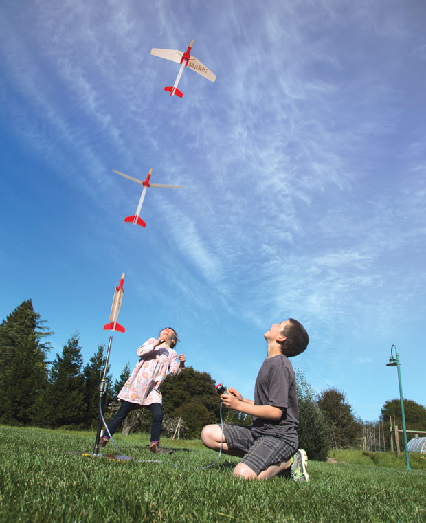
That same day we also happened to be launching our compressed air rockets. It’s the “maker way” to figure out fun ways to combine things — so the Air Rocket Glider (ARG) was born.

Here’s how to build your own Air Rocket Glider. You can also try our new kit (check out airrocketworks.com). Either way, it’s a lot of fun.

Project Steps

Print the plastic parts.

Download the part files and 3D-print them in ABS plastic at 100% fill: left fuselage, right fuselage, wing pivot halves (2), tail fins (3), and the 2-part nose mold (optional, see Step 2).

Cast the soft nose (optional).

Assemble the 2 halves of the nose mold and bolt it together with #10-32 screws, washers, and nuts. Mix about 20ml of urethane resin as indicated on the manufacturer’s label in a paper cup. Remove the plunger from the syringe, hold a paper towel over the tip of the syringe, and carefully pour the mixture into the barrel of the syringe. Insert the plunger, and turn the syringe upright. Allow the air bubble to rise to the tip of the syringe, and expel it.

Place the tip of the syringe into the large hole in the mold, then slowly and steadily inject the resin until a puddle forms on top of the mold at the small vent hole. Allow the resin to cure according to manufacturer’s instructions.

Optionally, you can 3D-print the soft nose in flexible filament at 100% fill. We’ve provided preconfigured .ini slicing files.

Fabricate the body tube.

Cut the body tube to 9″, using a hacksaw. Sand the ends smooth and perpendicular, and remove any burrs on the inside and outside of the tube at both ends, using 220 grit paper.

Mark a line down the length of the body tube with a pencil. I like to use the old rocket fin trick — press the tube into the corner of a doorjamb, and use the jamb as a guide to draw your line.

Download the paper template, print it at 100% scale, and cut out the fin guide. Wrap around the guide, align the Vertical Tail mark with the first pencil line, and draw pencil lines for the other 2 fins.

Assemble the fuselage.

Seat the rear end of the soft nose in its pocket in the left fuselage. Using 1/4″ lengths of filament in the corner holes as alignment pins, either Ø1.75mm or Ø3mm, super-glue and clamp the fuselage halves together, capturing the nose between.

Let the glue dry, then clean out the wing pivot hole using a 3/8″ drill bit if needed. Alternately, you can clean the hole with a rolled up piece of sand paper if needed.

TIP: A 3/8″ drill bit can be used in the large wing pivot hole to keep the halves aligned — just try not to glue it in place.

Assemble the wing pivot.

Carefully align the 2 halves of the wing pivot and glue them together. I like to make a simple U-shaped tool from a large paper clip to keep the holes aligned.

Test-fit the wing pivot in the fuselage and ensure that it rotates freely without binding. Sand down the glue seam or the outer faces of the wing pivot if needed.

Mount the body tube.

Glue the fuselage into the body tube using superglue. I like to apply it to the small diameter at the rear of the fuselage in a zig-zag pattern, and install the fuselage into the body tube with a twisting motion. Align the seam on the top of the fuselage with the Vertical Tail pencil line you marked on the tube. Work quickly, you only have a second or two before the glue sets up.

Mount the fins.

Wrap the sandpaper around the body tube, abrasive side outward, and move the base of each fin along the paper, to ensure a good surface and a matching radius to adhere the tail fins. Wrap a piece of masking tape around the body tube 2″ from the open end.

Apply superglue to the inside of the curved base of one of the fins. Carefully align the flat face of the fin with the Vertical Tail pencil line, and align the leading edge of the fin with the tape edge. Bond the fin in place. Bond the remaining 2 tail fins in place, aligning the flat faces with the marks on the fin spacing guide. Note that all 3 fins are identical, so the base of each fin will wrap around the body tube in the same direction. Remove the tape and pencil lines.

Build the wings.

Cut the balsa wings as shown on the printed template. Use sandpaper to round the leading and trailing edges. This will help prevent cracks and improve the aerodynamics.

Apply super glue to the top and bottom of the wing, 3/8″ out from the base edge. Align the notch in the wing reinforcement piece with the notch in the balsa wing, and quickly slide it onto the wing. There’s an internal stop that the balsa wood will touch, and you will feel it fully seat in place.

Now you’ll add the staples that will anchor the rubber band. Notice the staple location marked on each wing template. Overlay the template on the wing, and open a standard stapler into “tacking” mode. Place the wing on 2 layers of cardboard, and staple through each wing where indicated. Pull off the paper template, taking care not to dislodge the staple.

Apply superglue over the base of the staple on the underside of each wing. This will bond the staple in place and harden the balsa, reinforcing the wing around the staple.

Once the glue has cured, flip the wings over and bend the staple leg nearest to the middle of the wing down flat to the surface. Cover this leg with super glue. Also apply superglue to the base of leg of the staple that is standing straight up. Once the glue has cured, bend a small hook into the standing leg, with the point of the hook aiming toward the angled bend in the leading edge of the wing.

Bend the pivot wire.

Starting halfway down the length of the 9″ wire, use needlenose pliers to bend a gentle radius in the wire that matches the outer diameter of the body tube. The legs of the wire should be parallel to one another, and roughly equal in length — they don’t have to be perfect, you’ll trim them later.

Now grip the wire just below the midline of the tube, as shown, and make an approximate 100° forward bend in each leg of the wire. Again, the legs should be parallel after bending.

Assemble the moving parts.

Insert the rubber band through the upper hole in the fuselage. If needed, a short length of small-gauge wire can be bent in a U and used to thread the rubber band through the tube.

With the wing pivot installed in the fuselage, align the notches in the wing reinforcements with the holes in the wing pivot. Ensure the hooks formed by the staples are facing away from the body of the plane. Slide the bent wing pivot wire through the wing reinforcements, starting at the rear (trailing edge) of the wings. It should slide along the base edge of the wings, through the holes in the wing pivot, and out the leading edge of the wing. This may take a couple of tries to get it seated. Pivot the wings to ensure smooth operation. Mark the excess wire flush to the front edge of the wings, and trim to length.

Stretch the rubber band and hook each end of the band to the formed staple hook on each wing. Careful, as you can easily pull the rubber band out one side of the body.

Test your wings.

You should now be able to test the folding action of the wings. Start with the wings folded back.

When released, the wings will hinge forward on the pivot wire, and then rotate on the plastic pivot into gliding position. Ensure that they open quickly, evenly, and smoothly. If one side opens faster than the other, equalize the tension in the rubber band between the fuselage and the staple on each wing.

Now check the angles of the wings in the deployed position. The angle of attack — how the wings’ leading edges are raked slightly higher than the trailing edges — can be adjusted by altering the two 100° bends in the wing pivot wire.

The dihedral angle — how the wings angle upward from fuselage to wingtip — should be 3° to 6° as built here. You can alter it by adding tape or thin shims to the top of the wing where the wing pivot contacts the wing reinforcement at the base of each wing. Greater dihedral angle makes the plane more steady, but slightly reduces lift.

Balancing and tuning.

Due to the varying densities of balsa wood, it’s important to balance your Air Rocket Glider left to right. To do this, simply invert the plane and balance it so it can roll side to side on your fingertips. If one wing is heavier than the other, you can add bits of packing tape to the tip of the lighter wing until the plane balances evenly. This will help the plane fly straight and true.

If you’re flying your ARG in a smaller field or park, you can purposely weight one wingtip to upset the balance. This will cause the ARG to spiral down to the ground, and not drift too far from the launch site.

On windier days, a second rubber band can be added to increase the opening power of the wings. This will cause the wings to deploy slightly sooner, at a lower altitude, but will help prevent the wind from causing the plane to tumble or spin without opening its wings fully.

As the rubber band gets old and tired, it should be replaced to ensure proper wing operation. During storage, unhook the rubber band from the wings to prevent it from stretching.

Your Air Rocket Glider is complete!

Launching the Air Rocket Glider.

The ARG launches off of a 3/8″ NPT pipe about 12″ long, which is threaded on one end to connect to the launcher valve. A bent piece of wire holds the wings in the folded position until the ARG is launched. The new Compressed Air Rocket Launcher Version 2.0 kit includes this launch tube, adapter, and the wing holder wire.

If you have MAKE’s older Compressed Air Rocket launcher made from PVC pipe and a sprinkler valve, its existing launch tube is too large — but that’s easily remedied. Just remove the existing 1/2″ PVC launch tube (shown in white here), and swap it for the 3/8″ NPT pipe, 12″ long, that’s threaded on one end. Screw the 3/8″ pipe into a reducer bushing, 3/4″ male NPT to 3/8″ female NPT, then screw the reducer into your existing sprinkler valve.

Finally, bend the wing holder wire from an 18″ length of wire coat hanger as shown here, then install it onto the base of your new 3/8″ launch tube as shown.

Here’s the ARG on the launcher, with the wings held back by the bent wire, ready for launch!

Let us know how your Air Rocket Glider flies, and get involved in the growing air rocket community, at airrocketworks.com.