M39_SpecialSecial_VenusFlyTrap_Step2

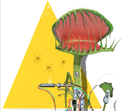
In this fun and easy project you’ll explore biorobotics — the intersection of biology and robotics — by creating a remote-controlled Venus flytrap that can close its leaf on our command! You’ll do this by connecting an Arduino microcontroller to specific locations on a leaf using a simple circuit and home-fabricated electrodes.

This project will teach you about how biological action potentials in plants and animals can be triggered using small electronic signals. Materials for the project cost under $40 (not counting the cost of the reusable Arduino) and take under 90 minutes to put together (plus around 24 hours for the flytrap to rest). It makes a great classroom demonstration.

You could even extend this project with a Wi-Fi connection and a second circuit to sense when the leaf closes — creating an internet-connected fly detection plant cyborg!

Final_Venusflytrap_MB_Make

How It Works

Much of the physical and biological world is driven by the passive movement of matter from high concentration to low concentration. In live organisms such as our Venus flytrap, plant cells utilize these concentration gradients to move ions — molecules that carry a charge. Ca2+ (calcium) and K+ (potassium) are positively charged; this means they need to gain electrons (e) in order to be stable. Cl (chloride) is negatively charged, meaning it needs to give up an electron to be stable. When the Venus flytrap moves ions such as Ca2+ and K+ around in its cells, the result is not only a change in the concentration of these ions, but also a change in the electronic charge.

Batteries take advantage of these exact same biochemical phenomena: one side of a battery is rich in electrons, and the other side is deficient in electrons. The electrons want to move from high concentrations to low concentrations but they’re separated by an impenetrable wall. They can only equilibrate when the two sides of the battery are connected by a wire, forming an electronic circuit.

So what happens if we stick a Venus flytrap in the middle of this circuit? From the plant’s perspective, electrons are dumped into the cellular space and the electricity “feels” like a change in ionic concentration.

When an insect stimulates the trigger hairs on the surface of a Venus flytrap, the cells of the trigger hair cause a change in ionic concentration. The corresponding change in electronic (e) charge causes the cells that join the two lobes of the leaf, called the midrib, to rapidly swell with water, causing the trap to close. In this way we can use electricity to simulate a fly landing on the surface of the trap and trigger a biological response. The truth is, biological organisms have been using electricity since long before we ever figured it out!

For this exercise you’ll be connecting and controlling our Venus flytrap in these easy steps. Let’s make a plant cyborg!

Project Steps

Make the electrodes.

You’ll treat one end of each silver wire with bleach to form a layer of silver chloride. Put the bleach in the shot glass and note its level. You’ll make both electrodes at the same time. Twist each silver wire around the toothpick, leaving 1″ or so to dangle, so that 1cm of one end may be submerged into the household bleach.

Place the toothpick on top of the glass and allow the wires to react and form a layer of silver chloride. They’ll look tarnished when they’re done. This should take about 15 minutes.

Unwind the wires from the toothpick and rinse them well under a running tap.

Place the electrodes.

With your fingers, carefully insert one electrode through the midrib of the Venus flytrap leaf. It may close — this is OK.

Insert the second electrode through the middle of one of the leaf’s 2 lobes.

Separate and tape each electrode wire to the side of the plant’s pot — this will reduce the movement of the electrodes when we connect them to our circuit later.

Build the circuit: place resistors.

Connect the AA battery holder’s positive (red) wire to one of the breadboard voltage rails, and its negative (black) wire to another breadboard voltage rail. Then follow the layout diagram to place the resistors, op-amp, and jumper wires as shown.

Take one 10kΩ resistor. Place one leg into the positive voltage rail and the other into a row near (but not connected to) the op-amp IC.

Take the other 10kΩ resistor. Place one leg into the same row as the first resistor — so they’re connected to one another — and place the second leg into the negative voltage rail.

To test the circuit, insert the batteries into the battery holder. Place your multimeter’s red probe on the resistor leg that’s connected to the positive voltage rail. Connect the black probe to the negative voltage rail. The multimeter should read approximately 3.0V, or a little more. Next, move the red probe to where the resistors connect to each other. The multimeter should read half of the value observed when measuring from rail-to-rail.

Disconnect the red wire of the AA battery holder from the breadboard.

Place the op-amp IC.

Insert the operational amplifier IC across the gap in the center of the breadboard. Place it near (but not yet connected to) the 2 resistors. Orient pin 1 of the IC to be closest to the negative voltage rail.

Using jumper wires, connect the op-amp’s pin 8 to the positive voltage rail; pin 4 to the negative voltage rail; pin 1 to pin 2; and pin 3 to the row where the 10kΩ resistors are connected to one another. Connect a second wire to pin 1 and leave the other end of the wire free.

To test the circuit, reconnect the red wire of the AA battery holder to the breadboard. Touch the multimeter’s red probe to pin 8 and the black probe to pin 4. It should read approximately 3.0V. Next, touch the red probe to pin 1 and the black probe to pin 4. It should read exactly half of the value from rail-to-rail.

Set up the Arduino.

Set your breadboard aside for a moment and get your Arduino set up and tested. This will allow you to connect it to your circuit with confidence and avoid any misfires. Connect the USB cable between your computer and the Arduino. Launch the Arduino software and select File→ Examples → 01.Basics → Blink.

To test the Arduino, press the Upload button and select the appropriate USB port (e.g., /dev/cu.usbmodem1421). After the program has been loaded to the Arduino, you’ll see the small light near the center of the board begin to blink. Unplug the USB cable to power off the Arduino.

Place the optocoupler IC.

Insert the optocoupler IC across an empty slot in the breadboard. Orient pin 1 of the IC to be closest to the negative voltage rail.

Using jumper wires, connect the octocoupler’s 4 pins as follows: pin 1 to pin 2 of the Arduino; pin 2 to a GND pin on the Arduino; pin 3 to the negative voltage rail on the breadboard; and pin 4 to one end of a jumper wire. Allow the other end of the wire to remain free.

Test the whole circuit.

Reconnect the red wire of the AA battery holder to the breadboard.

Enter the following code in the Arduino IDE software:


/*

 VenusTrigger


 A simple sketch to actuate the closure of a

 venus flytrap leaf using a simple circuit.


 Wait to receive a character on the serial port,

 then cause pin 2 to go high for 5 seconds. 


 Distributed under the GPLv2 public license.


 Author: jordan.husney@gmail.com

 (c) 2013

 */


int incomingByte = 0;


void setup() {

  Serial.begin(9600);

  pinMode(2, OUTPUT);

  digitalWrite(2, LOW);  

}


void loop()

{

  Serial.print("Waiting for keypress: ");

  while (Serial.available() == 0) {

    // Just hang out;

  }


  incomingByte = Serial.read();

  Serial.println("triggered!");


  digitalWrite(2, HIGH);

  delay(5000);

  digitalWrite(2, LOW);

}

Upload it to the Arduino by pressing the Upload button. Go to Tools → Serial Monitor (or press ⇧⌘M) to open the Serial Monitor window, where you can interact with your running Arduino sketch. In the blank, enter “hi” and press the Send button. You should see the text Triggered! followed by Waiting for keypress: in the window.

Using the multimeter, touch the red probe to the optocoupler’s pin 1 and the black probe to its pin 2. You should see 0V (off). Send “hi” again using the Serial Monitor. You should see the multimeter read 5V for 5 seconds. (You may need a friend to help you with these contortions.)

Next, touch the red probe to both the op-amp’s free jumper wire and the optocoupler’s free jumper wire. It should read 0V. Press another key in the Arduino Serial monitor. It should read approximately 1.5V for 5 seconds. You’re ready to connect to a real plant!

Actuate your robotic plant!

Wait for the Venus flytrap leaf to fully open again. (This may take between 12 and 72 hours.) Now it’s time to impress your friends.

Connect the the op-amp’s free jumper wire to the silver electrode wire attached to the leaf midrib by wrapping the free end of the electrode wire around the conductive end of the jumper wire.

Connect the optocoupler’s free jumper wire to the silver electrode wire attached to the middle of the leaf. The leaf should remain open.

In the Arduino’s Serial Monitor window, prepare to press a key. On the count of 3, say, “Fire in the hole!” and press a key. The leaf should close! If it doesn’t, try zapping it again. Sometimes it takes 2 or 3 pulses. You now have robotic command of a flesh-eating plant!

Circuit Theory

How does this circuit work? The 2 resistors are used as a voltage divider: the place where the resistors connect to each other is exactly half of total battery voltage. This voltage is presented to one of the inputs of the operational amplifier. The op-amp is wired as an analog buffer — whatever input voltage it “sees” from the resistors, it passes to its output. The low voltage output from the op-amp is attached directly to the Venus flytrap’s leaf via one of the electrodes.

The other electrode is attached to the optocoupler. The optocoupler isolates the Venus flytrap from the “dangerous” voltages of the Arduino and connects it instead to the “safe” voltages from the batteries. Inside the optocoupler is a little LED and a photodetector. This LED is powered on when the Arduino sends a pulse. When the photodetector detects the light from the LED, it switches on and allows the current to flow through the leaf, causing it to close. It’s essentially acting as a transistor, and in truth, a transistor would probably work here. But using light to make connections is a smart precaution when connecting to organisms. For example, all medical diagnostic equipment uses this kind of isolation. Optocouplers are designed to fail as open circuits. Other kinds of switches, such as a transistor, can fail as a short circuit — which could harm or kill the organism.

Exploring Possibilities

Now that you’ve made your remote-controlled Venus flytrap, you’ve probably got a million ideas on how you’re going to use it. However, if you’re short on ideas (or open to suggestions) we’ve got a few.

The Arduino is used in this circuit to provide a 5-second pulse. The only role the computer plays is to provide a ready input method — your keyboard — to instruct the Arduino when to actuate the circuit. Consider using a WiFi or XBee Arduino shield to make a wireless Venus flytrap.

If you’re very ambitious, it should be possible to use the electrodes attached to the Venus flytrap as a cybernetic fly detector. When the trigger hairs on a leaf are stimulated, a very small voltage spike (only 0.14V) will briefly (<2ms) appear across the electrodes. You can detect this small change using a chip known as an instrumentation amplifier such as an Analog Devices AD623. It can take the small signal from the leaf of the plant and amplify it hundreds or thousands of times to a larger voltage that can be detected by a microprocessor, such as an Arduino. If you pull this off, consider sharing your circuit design with the world!