Naghi Sotoudeh is a robotics, automation, and electronics designer from Ardabil, Iran. He earned a BS in electrical engineering from Islamic Azad University in 2009. He now lives in Tehran and works as a circuit designer and programmer for Faratel Electronics.
Rizeh is a Persian word that means “tiny,” and our Rizeh robot is very small indeed. Driven by two cellphone vibrators, it’s very low-cost to build and implement. The robot is able to perform basic linear and circular motions, and with its infrared detectors it can successfully follow a black line on a white background. To our knowledge it’s the smallest line-following vibrobot in the world!
We applied some techniques to minimize the electronics needed to control the robot, which is crucial in building small bots. Instead of a motor driver, our control scheme employs the internal PWM capabilities of the microcontroller itself to control the vibrators. The final robot weighs just 5 grams and measures 19mm×16mm×10mm.
Our line-following test includes curves, lines, and corners, and the robot is able to successfully follow the line. Rizeh won first place at RoboCup IranOpen 2013 in the Demo (Freestyle) League. Here’s how you can make it.
Special thanks to Prof. Adel Akbarimajd,my partner in this project.
Download the printed circuit board (PCB) files and make your PCB. We’ve provided DXF files for milling, and Gerber files for etching; grab the free download here.
This one was milled on a ShopBot Desktop at the MAKE Labs.
Download the code from the parts list, then upload the .hex file to the ATtiny microcontroller using AVRDUDE or similar software on your computer, and an AVR programmer. (If you haven’t done this before, you can follow Adafruit’s tutorial at learn.adafruit.com/usbtinyisp/avrdude.) You’ll want to connect the ATtiny to an 8SOIC-to-8DIP breakout board to access its tiny pins.
Bend or cut off the microcontroller’s pin 1 (the reset pin) so it won’t contact the ground trace below it on the PCB. Then assemble and solder the components to their locations on the PCB — microcontroller, IR sensors, resistor, LED, and pin header — and use double-stick tape to mount the battery. You’ll use its 2mm JST header to plug it into your pin header (with a little wiggling).
Solder the 2 leads for each vibrator motor as shown, paying close attention to wire colors and polarity. For the robot’s right motor (shown in the diagram), connect the blue, negative (–) wire to the ground trace right after the LED, and connect the red, positive (+) wire to a trace leading to the ATtiny chip. For the robot’s left motor (shown in the diagram) connect its blue, negative wire to a trace leading to the ATtiny, and its red, positive wire to a large ground trace above the ATtiny’s ground pin.
Finally, solder jumpers J1 and J2 where indicated.
Remove the adhesive tape backing from each vibrator motor, then mount them to opposite edges of the circuit board as shown. You can use additional foam tape for strength, or wrap them instead with 2 turns of single-sided tape, but take care not to block the sensors.
Use your wire cutters to cut 3 pins or needles down to size: 12mm (2) and 13mm (1). With the robot PCB upside-down (components facing you), tape a 12mm stand to each vibrator, centered with their points straight up. Mount the 13mm stand centered at the robot’s “head” using more tape or a dab of epoxy. Your robot is complete.
Build your test track and test your tiny line-follower!
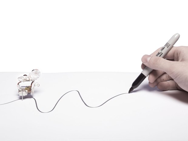
Draw the route you want the robot to follow on a white sheet of craft foam, using a black marking pen with a 6mm-wide tip. The track surface needs to be made from soft material so that the legs get traction and don’t skip too much.
Connect the battery to turn your robot on. Hold it upside down in the air for a few seconds to calibrate the sensors. Then put the robot on the path you drew and enjoy your tiny robot’s movement! If it’s skittish, try adjusting the length of the “head” pin or moving the battery forward to keep weight on the head.
Conclusion
How It Works
The microcontroller compares the 2 sensor inputs to see which one is detecting a brighter background, and activates the motor on that side. The triangular arrangement of the pins causes the vibrating side to “walk” forward, rotating the robot around the head pin toward the opposite side. Result: the robot continually moves forward, always redirecting itself toward the center of the dark line. For more information and video, visit roborizeh.ir and read our paper in Advanced Robotics, “Design and motion analysis of vibration-driven small robot Rizeh.”
Naghi Sotoudeh is a robotics, automation, and electronics designer from Ardabil, Iran. He earned a BS in electrical engineering from Islamic Azad University in 2009. He now lives in Tehran and works as a circuit designer and programmer for Faratel Electronics.
When you buy through links on our site, we may earn an affiliate commission.
Our websites use cookies to improve your browsing experience. Some of these are essential for the basic functionalities of our websites. In addition, we use third-party cookies to help us analyze and understand usage. These will be stored in your browser only with your consent and you have the option to opt-out. Your choice here will be recorded for all Make.co Websites.
Allow Non-Necessary Cookies
Escape to an island of imagination + innovation as Maker Faire Bay Area returns for its 15th iteration!
Buy Tickets today! SAVE 15% and lock-in your preferred date(s).