Conclusion
Additional Activities for the Electronics Springboard
In Project Make, electronics instruction begins with guided experimentation using conductive playdough and electronic components found in the Squishy Circuits kit. Students experience fundamental concepts such as polarity, open and closed circuits, series and parallel circuits, short circuits, switches and more using a friendly familiar model.
We then use Charles Pratt’s excellent
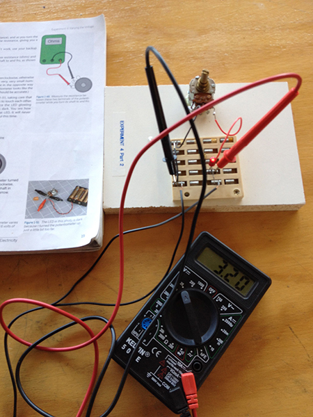
Make: Electronics which uses on hands-on experiments as the framework for further study. Students learn the basics of multimeter usage, components are introduced as they are needed for specific experiments and a bit of history and theory (even some math!) is sprinkled throughout. The springboard replaces jumper wires with alligator clips in the early
Make: Electronics experiments. The small boards pictured for Experiment 3 and 4 are the first projects I made using a springboard and are still in use today.

The history of how this tool made it into our curriculum and how its use has evolved is one that illustrates some of the unique aspects of a having a class centered around maker principles. Over the summer, we received a donation of old electronics parts from a retired teacher that included a number of large boards with 144 springs arranged in a 10 x 12 array. I immediately saw the benefits of these relics and thought of designing a smaller model to be made using our laser cutter. My skills weren’t quite developed enough to allow me to get the job done by the time I planned to begin the lesson, so I hacked up a couple of the big boards, attached them to a piece of scrap wood using epoxy and called it version 1.0.

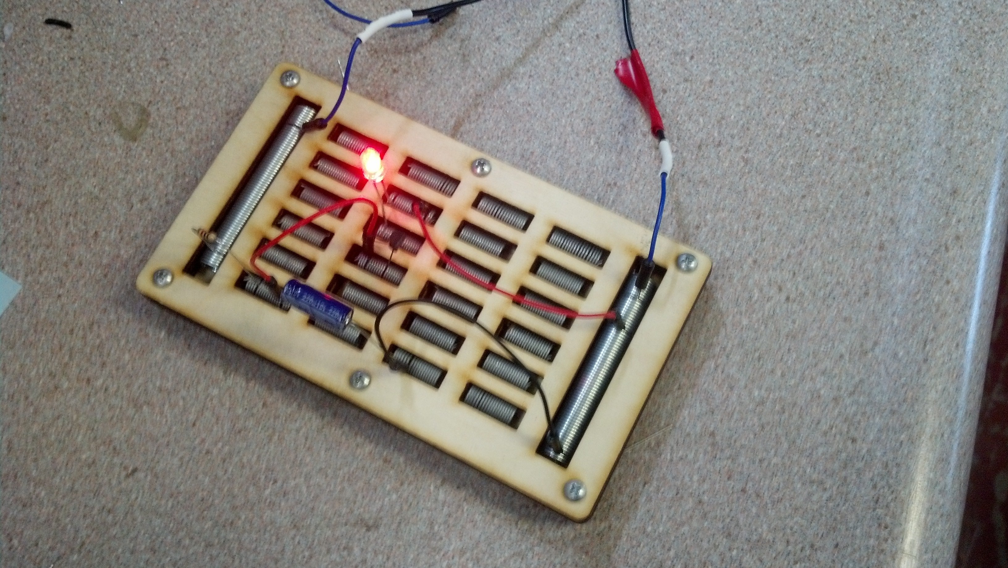
I have since made several laser cut versions (
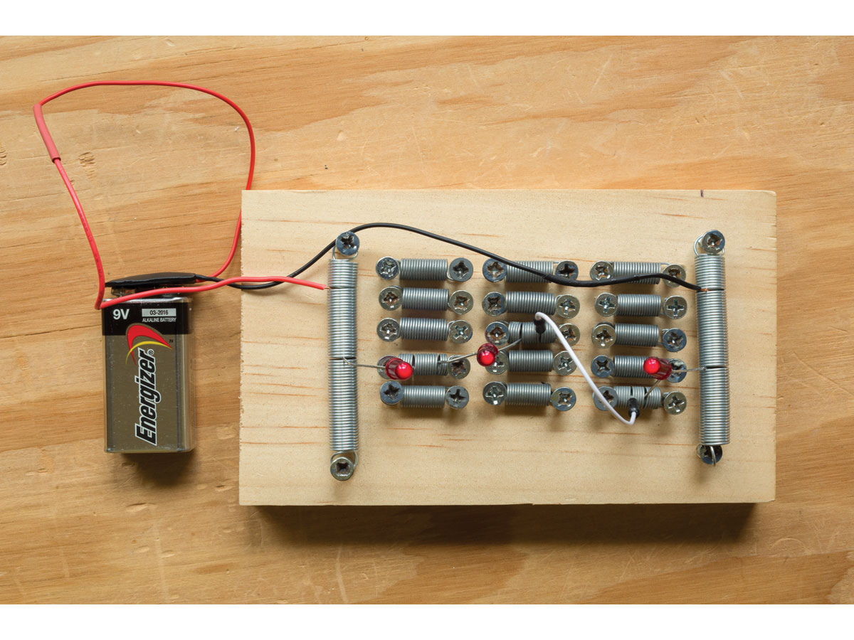
attached design file created in Inkscape using layers for the different cuts), but have come to appreciate the added value of having students make the simple boards shown in the article. Measuring and laying out the springs, combined with the use of tools ranging from handsaws to chop saws and hammers to portable drills serves as a nice introductory project with skills which transfer to other more complicated projects down the road. At the end of the lesson most are dismantled so that the parts can be used again, I keep the best one or two as examples for future classes.

The most complicated projects that we usually do on a springboard are LED flashing capacitor-transistor circuits like
this one from Madlab, after which they move on to modern breadboards for more complicated projects using ICs.


