One nice thing about gears is that if you know any two things about them – let’s say outer diameter and number of teeth — you can use some simple equations to find everything else you need to know, including the correct center distance between them. In this project, we’ll design and fabricate spur gears using free software (Inkscape) and an online store (Ponoko.com) that does custom laser cutting at affordable prices out of a variety of materials. If you have access to a laser cutter at a local school or hackerspace, even better! You can also print out the template and fix it to cardboard or wood to cut the gears by hand.

This project is adapted from a blog post a student did in my first Mechanisms and Things That Move class at NYU’s ITP.

Project Steps

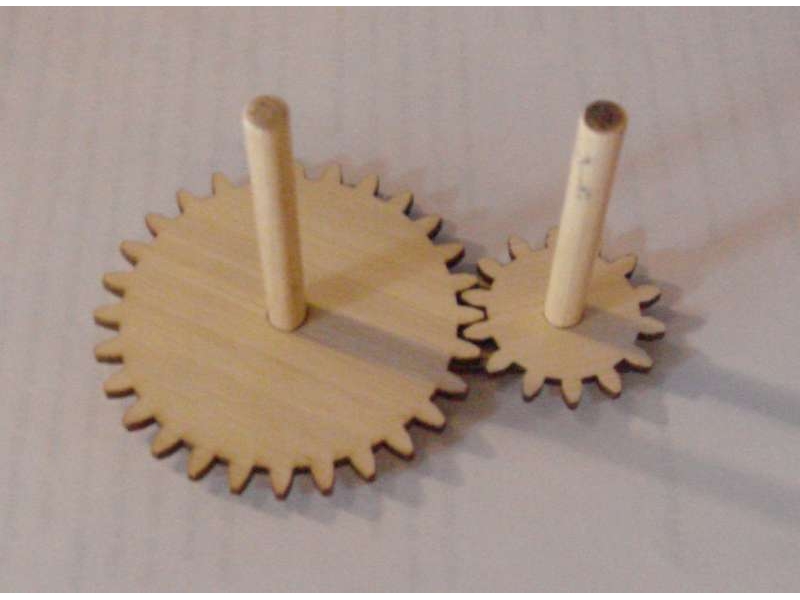
First, look over the anatomy of the spur gear pair in this figure and the vocab below.

Number of Teeth (N)

Pitch Diameter (D): The circle on which two gears effectively mesh, about halfway through the tooth. The pitch diameters of two gears will be tangent when the centers are spaced correctly.

Diametral Pitch (P): The number of teeth per inch of the circumference of the pitch diameter. Think of it as the density of teeth — the higher the number, the smaller and more closely spaced the teeth on a gear. Common diametral pitches for hobby-size projects are 24, 32, and 48. The diametral pitch of all meshing gears must be the same.

Circular Pitch (p) = pi / P: The length of the arc between the center of one tooth and the center of a tooth next to it. This is just pi (π = 3.14) divided by the diametral pitch (P). Although rarely used to identify off-the-shelf gears, you may need this parameter when modeling gears in 2D and 3D software like we’re doing here. As with diametral pitch, the circular pitch of all meshing gears must be the same.

Outside Diameter (Do): The biggest circle that touches the edges of the gear teeth. You can measure this using a caliper like Sparkfun.com’s # TOL-00067. Note: Gears with an even number of teeth are easiest to measure, since each tooth has another tooth directly across the gear. On a gear with an odd number of teeth, if you draw a line from the center of one tooth straight through the center across the gear, the line will fall between two teeth. So, just be careful using outside diameter in your calculations if you estimated it from a gear with an odd number of teeth.

Center Distance (C): Half the pitch diameter of the first gear plus half the pitch diameter of the second gear will equal the correct center distance. This spacing is critical for creating smooth-running gears.

Pressure Angle: The angle between the line of action (how the contact point between gear teeth travels as they rotate) and the line tangent to the pitch circle. Standard pressure angles are, for some reason, 14.5° and 20°. A pressure angle of 20° is better for small gears (and gears with few teeth), but it doesn’t make much difference. It’s not important to understand this parameter, just to know that the pressure angle of all meshing gears must be the same.

All of these gear parameters relate to each other with simple equations. The equations in the table here come from the excellent (and free) design guide published by Boston Gear [PDF].

Download and install Inkscape from http://www.inkscape.org. It’s a free, open-source vector-based drawing program similar to Adobe Illustrator. It plays well with most modern Windows, Mac, and Linux operating systems (check FAQ for details).

Go to http://www.ponoko.com/make-and-sell/down… and download their Inkscape starter kit. This will give you a making guide (a PDF file) and three templates that relate to the sizes of materials Ponoko stocks. Unzip the file and save to somewhere you’ll remember.

Open a new file in Inkscape. Under the File menu, go to Document Properties to get the window shown here. Change the default units in the upper right hand corner to inches. Back in the main window, change the rulers from pixels to inches in the toolbar. Your screen should look like this. Once set, exit that window.

Now let’s make some gears! Go to the toolbar and choose Extensions –> Render –> Gear. A small Gear window will pop up that gives you three options: Number of Teeth, Circular pitch, px, and Pressure angle. Leave Pressure angle alone — the 20° default is standard for off-the-shelf gears so it’s a good place to start. In this figure you can see that I chose 28 teeth with a circular pitch of 24. Click Apply, then Close.

Note on circular pitch: In Inkscape, the circular pitch is given in pixels, not inches, as we’re used to using in the equations in the above table. You can get different gear ratios by just choosing a circular pitch that looks good and varying the teeth number, but if you want to make gears that interface with off-the-shelf gears, you need to pay a little bit more attention. By default in Inkscape there are 90 pixels in 1 inch. So if you set circular pitch to 24px in the gear tool as done above, that rounds to 0.267 inches (24/90 = 0.2666…).

Since diametral pitch (P) = π / circular pitch (p), the diametral pitch (P) in inches is = π / 0.267 = 11.781. You will not find any off-the-shelf gears with a diametral pitch of 11.781. As mentioned earlier, common diametral pitches are 24, 32, and 48. So if you plan to make gears to play nice with off-the-shelf gears, start with the diametral pitch of your off-the-shelf gear and use the equations in the table to work backwards to what your circular pitch should be in pixels in Inkscape.

Now, since one gear is no fun by itself, follow the last two steps again to make at least one more gear. The second gear shown in figure 30 has 14 teeth. Remember: The pressure angle and circular pitch must be the same for the gears to mesh – only change the number of teeth!

Use the circle tool and hold down the CTRL button (on a PC) to draw a circle inside the big gear. The default circle shows up filled in with black. Zoom in if you need to. Make sure the arrow selector is active and click on the circle. Make sure inches is selected in the toolbar and the lock button looks locked. Type 0.250 in the W box in the toolbar, press enter, and watch the H box change automatically. Your circle will resize to 0.250 inches in diameter and your screen should look like this.

Click and drag a box around the big gear, small gear, and circle shape to select them all. From the menu bar, choose Object –> Fill and Stroke. A window that looks like this should pop up.

In the Fill tab, click the X button for no paint.

In the Stroke paint tab, click the button next to the X for flat color. Leave the color default (black) for now.

In the Stroke style tab, change the width to 0.030 mm and hit Enter. This is what Ponoko wants the line thickness to be for laser cuts. Adjust if necessary if you’re using a different laser cutter. Close the window.

Now we need to get this circle in the exact center of the gear. Make sure the arrow selector is active. Click and drag a box around the big gear and the circle to select them both. On the menu bar, go to Object –> Align and Distribute. Click on the “center object horizontally” button highlighted here, then the one right below it – “center objects vertically.” Now you have a gear with a hole perfectly centered! Copy and paste this circle and repeat this step to center a circle in the other gear.

Now that we have our gears, let’s create a base with holes spaced the correct distance apart so we can mount the gears with 1/4″ wooden dowels and make them spin.

First, we need to calculate what the center distance (CD) of our gears is using the equations from the table. Both of our gears have a circular pitch of 24 px and a pressure angle of 20°. The big gear has 28 teeth and the small one has 14. In the note on step 4, we converted the circular pitch in pixels to a diametral pitch in inches of 11.781. If we look at the table, all we need is that number and the numbers of teeth on the two meshing gears to find the center distance (CD). Use the equation CD = (N1 + N2)/2P and you’ll find that CD = 1.783.

Now, copy one of the circles inside the gears, and paste two of them about two inches apart on the lower part of the template. Select the one farthest to the left, and change the X coordinate in the toolbar to 3 inches, then hit Enter. Your screen should look like this.

Use the same procedure to place the second circle to the right of the first with an X coordinate of 4.783. This is the center distance we calculated above (1.783) added to the X coordinate of the first circle (3.000).

Now draw a rectangle around the two circles to complete the base. Align the rectangle with the two circles as shown here.

Now we need to prepare the file to be uploaded and ordered on Ponoko.com.

Ponoko uses colors to indicate how they should treat the files — for example, a blue 0.030 mm line means cut it all the way through. So select everything you’ve drawn so far, go to the color swatches at the bottom of the screen, and hold down the shift button while you click on blue.

Open the P1.svg template you downloaded earlier. Select everything you have drawn so far, and copy and paste it into this template as shown here. Don’t worry about the orange border and words — Ponoko knows only to cut the blue outlines.

Save the file and go to Ponoko.com to set up a free account, upload it, pick a material, and get it shipped! I chose blonde bamboo as shown here and the total cost was just $4.13 (plus shipping).

Note: Once you open your free account, go to My Accounts –> Preferences to set your shipping hub to “Ponoko – United States” (or the closest location to you). Mine was accidentally set to New Zealand so my shipping charges were curiously high until I figured this out.

Your Ponoko order should arrive in a couple of weeks, unless you specify a rush. While you’re waiting, get a 1/4″ wooden dowel from your local hardware or craft store (or McMaster-Carr, of course). Cut off two 2″ sections with a hobby knife and file down any splintery ends.

The gears will come in the square template with a sticky paper protector on each side. Peel off the paper, pop out the gears, and position the two gears over the holes in the base. Insert your wooden dowels, and voilà!

Conclusion

This project is an excerpt from my upcoming book, Making Things Move.