A few days ago, a friend told me that he saw a similar project on ThisIsWhyImBroke.com, and asked me to build one. Unfortunately, like my green lantern ring, I forgot to take a picture of the one I made for him so I built a simpler but less good-looking one of my own.

This guide looks fairly complex at a glance, but the only hard parts are the circuit and getting the switch to line up with the bottom plate. Also, the first step explains how to make a cardboard box cube, like the one I have at home. While the fifth step should be a project in its own right, it’s not very complicated, just a longer process.

Project Steps

The first step is to make the block itself. This can take anywhere from five minutes to hours depending on how you want it to look.

My first version was acrylic, but as I said earlier, my friend paid me to build that one so he has it now. My second version was just paper (it broke far too easily), and the third was a cardboard box.

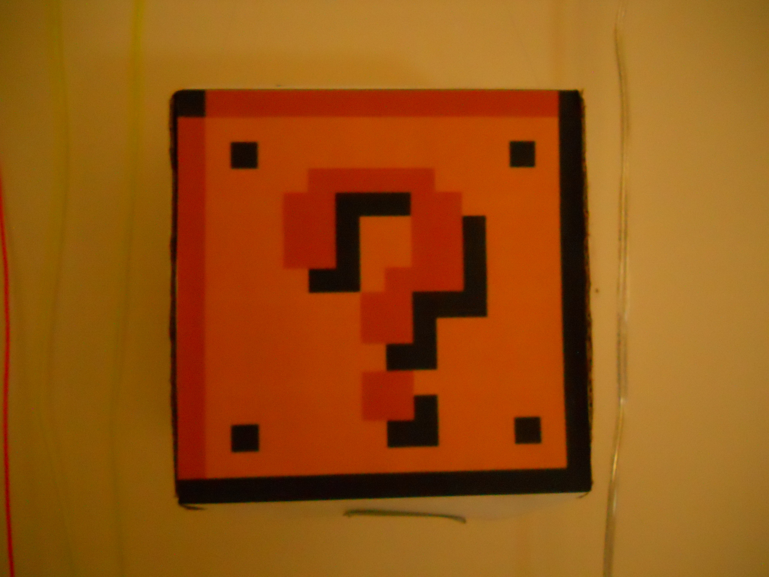
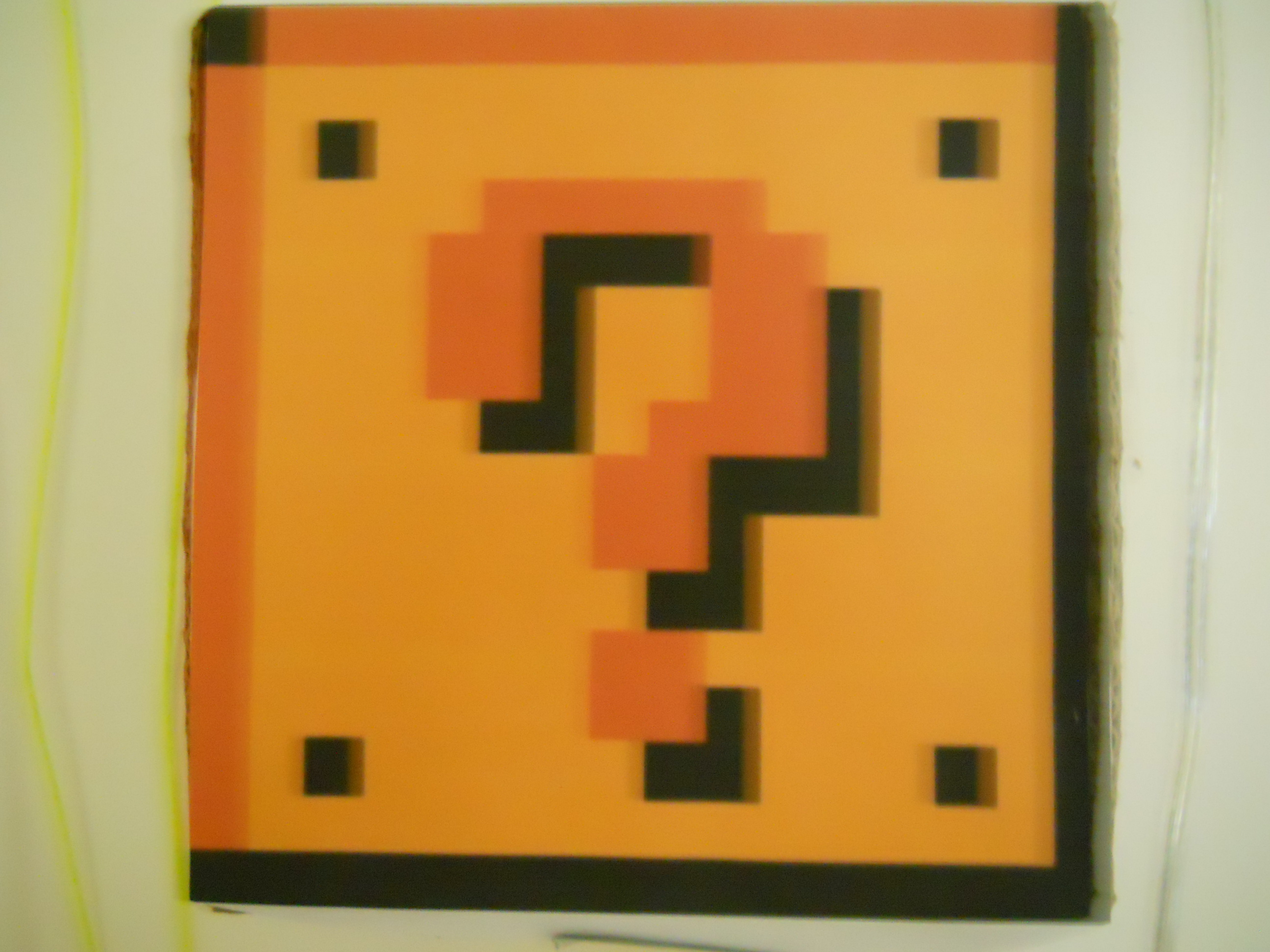
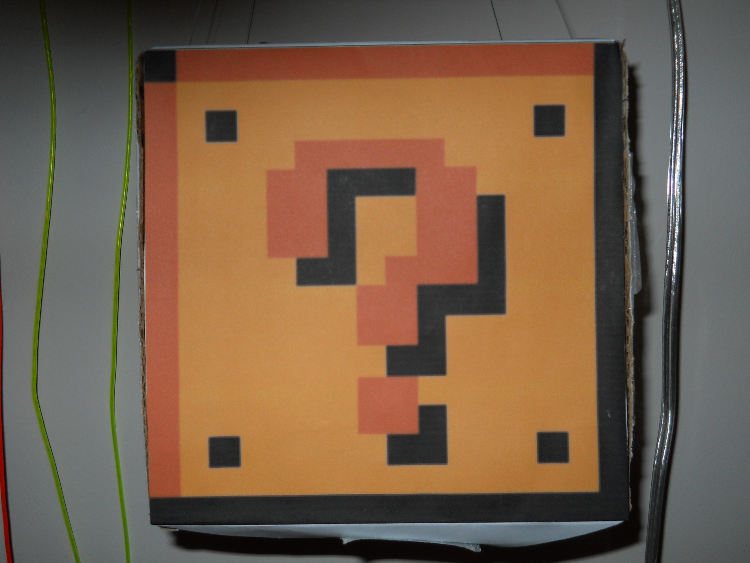
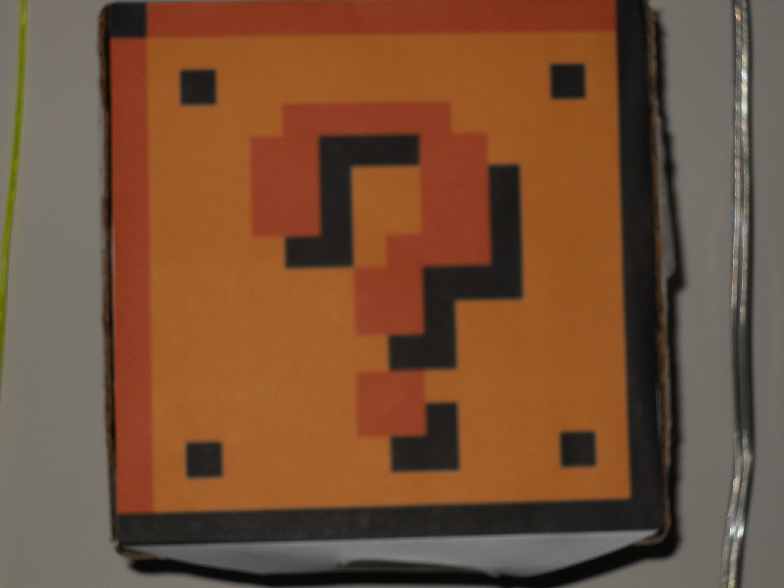
To make the basic lamp, just find a roughly cubeular cardboard box, and measure the dimensions of the top. Then, save a picture of the Mario block (a google search brings up hundreds of pictures), then scale it in any photo program (I used Microsoft Publisher). Then, just print it out.

If you want question marks on all sides of the box, print 4 or 5. If you don’t, just print one. Cut out the block(s), but make sure to leave tabs on the top and bottom. Now, cut the top flaps off of the top of the box, and cut a small hole in one side, slightly larger than your switch.

Spray paint the box if you like, or if you made 4-5 prints then you don’t need to. Use clear tape or glue to attach them to the faces of the box, however, do not tape/glue the bottom or sides of one of the faces. This way, you will still be able to get inside.

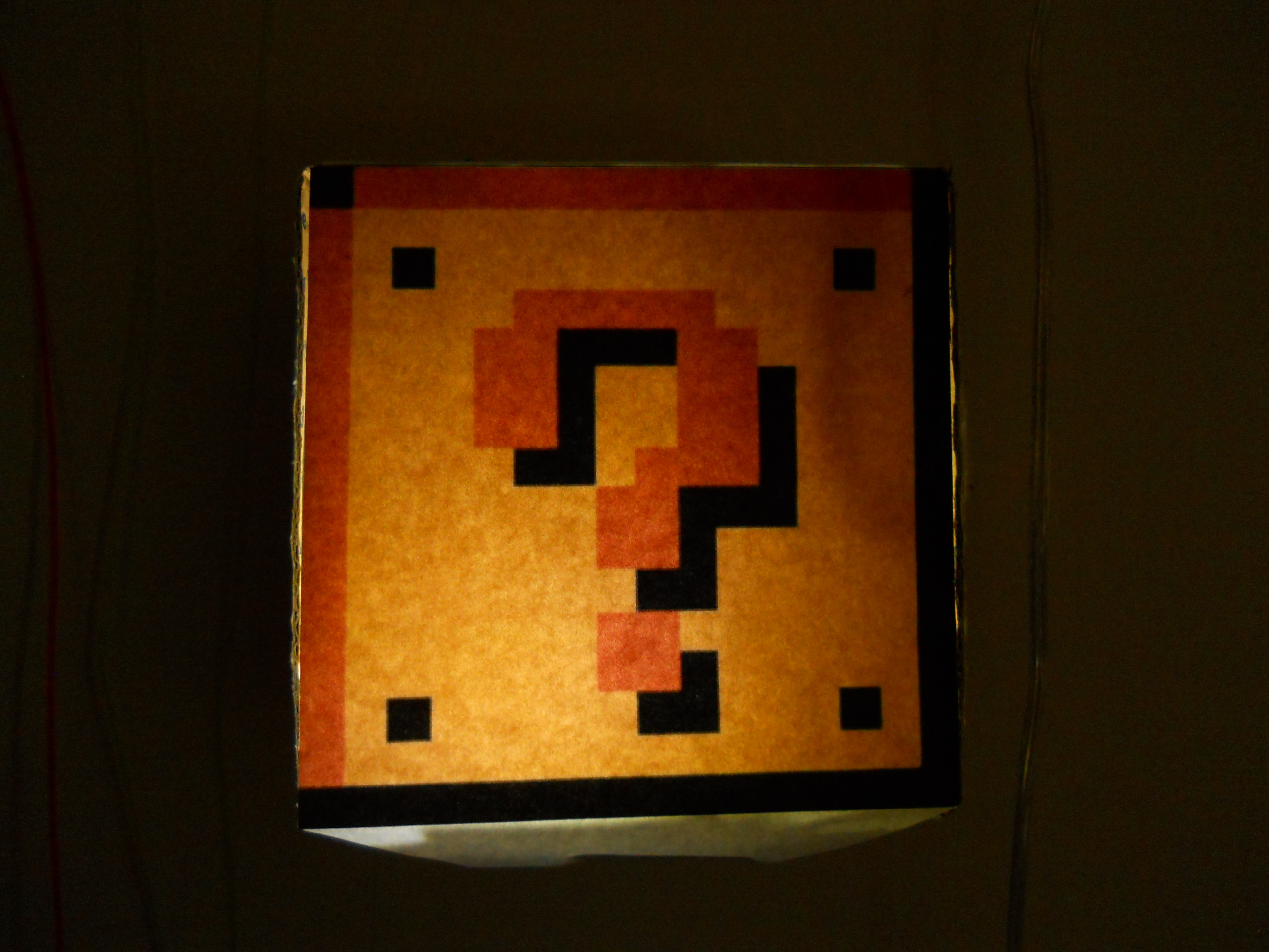
If you did it correctly, you should have an openable block. If you prefer a better model than a cardboard box, refer to the last step.

Edit: I recently found another mario coin block build here:http://www.instructables.com/id/Coin-blo…. This one dispenses coins instead, so check it out! You could also modify that block to incorperate the light.

Now comes the fun part, circuits.

The first circuit is NOT the circuit we will use in the block, but was the circuit I modified for this project.

The second circuit is what we will be using. When the switch brings the input low, it causes the circuit to oscillate, like a basic “transistor LED flasher” circuit. When the connection is broken, however, it stops oscillating and leaves one of the LEDs turned on.

In this way, “bumping” the switch will toggle the LEDs. The transistor on the far left is a power transistor, and it powers the 3W LED whenever the left small LED is turned on.

To assemble the circuit, I suggest using a breadboard first, and making sure everything works before soldering everything. If it does, solder it all up, but first, attach the TO-220 heatsink to the TIP42. Also, solder the HP LED on wires at least the length of your box, and add the other TO-220 heatsink to it.

Now, test your circuit, and if it works, then place the battery and circuit in the bottom of the box. Push the switch through the hole you made earlier, and glue it in place.

Position the LED at the back of the box, facing the front.

Test out the lamp by tapping the switch. The LED should turn on and be diffused by the paper in front.

Now, tape another piece of cardboard to the bottom of the box, hanging down just enough that it doesn’t press the switch.

Test it again.

If everything works, then close up the last side (but do not tape/glue it; you will need to replace the batteries eventually).

Poke some pinholes in the top, and run fishing line through if you want to hang it. If you’d rather mount it, then just cut a notch in the back to put the screw in.

Test it one last time.

Go save the princess!

If you want a “better” block, then I suggest small acrylic sheets. They are about $1.5 from Lowe’s for a page-sized sheet. Cut each into a square, and print out a coin block picture that size for each side (or if you prefer, use a brick pattern for some or all of the sides). Cut an additional square without a pattern. This will be the bottom.

Lightly sand each acrylic square, then cut out the paper printouts. Spray the acrylic with spray adhesive, and then place the printout on top. Do this for all 6. If you want to, add a coat of varnish or spray polyurethane to give it a nicer finish.

Place the extra sheets on top of each other, and use them as a square form for the other four. Use a strip of painter’s tape on the outside to hold them together, then add a bead of plastic glue on the inside. Once that is dry, remove one of the two flat sheets.

Next, push the bottom piece up the distance your switch mounts above the board, place a bead of glue around the perimeter of the sheet, then wipe off any excess glue and let it dry. Then, take the fifth printed sheet and place it on top of the box. Put a strip of clear tape on the inside and outside of one edge, making a hinged top.

Finally, add a thin strip of velcro on the side opposite the hinge, to hold down the top. Cut a hole in the middle of the bottom sheet to fit the switch. Add the switch. Then, glue the final printed sheet to the switch; it should mount flush with the bottom of the box. Ta-da! You’re done. If you weren’t confused by these directions, I’m impressed!

Conclusion

The parts list seems long, but the only uncommon parts are the LED, and maybe the transistor. The box can be any kind of cubeular box that you can drill through, and feel safe punching.