


Projects from Make: Magazine
Mimicking Robotic Arm
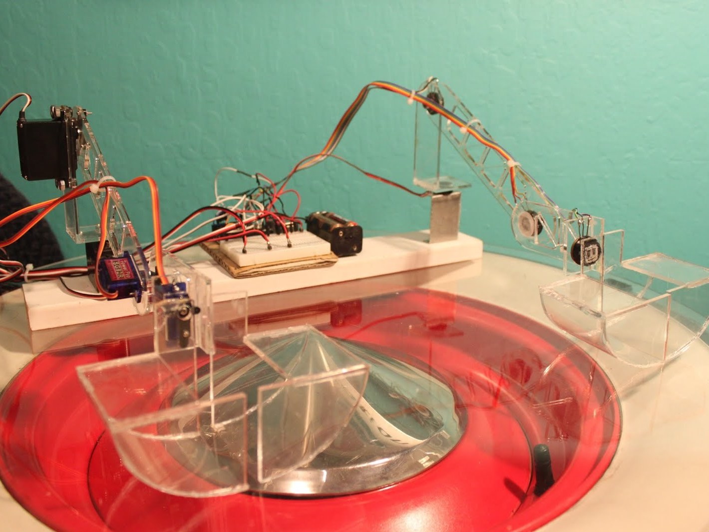
This project is for two robotic arms. One has potentiometers on the joints, and the other has servos. When you manipulate the potentiometer arm, the servo arm mimicks it using the arduino.
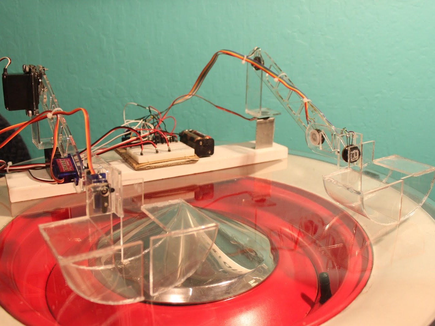
This project is for two robotic arms. One has potentiometers on the joints, and the other has servos. When you manipulate the potentiometer arm, the servo arm mimicks it using the arduino.

Gathering parts and potentiometers
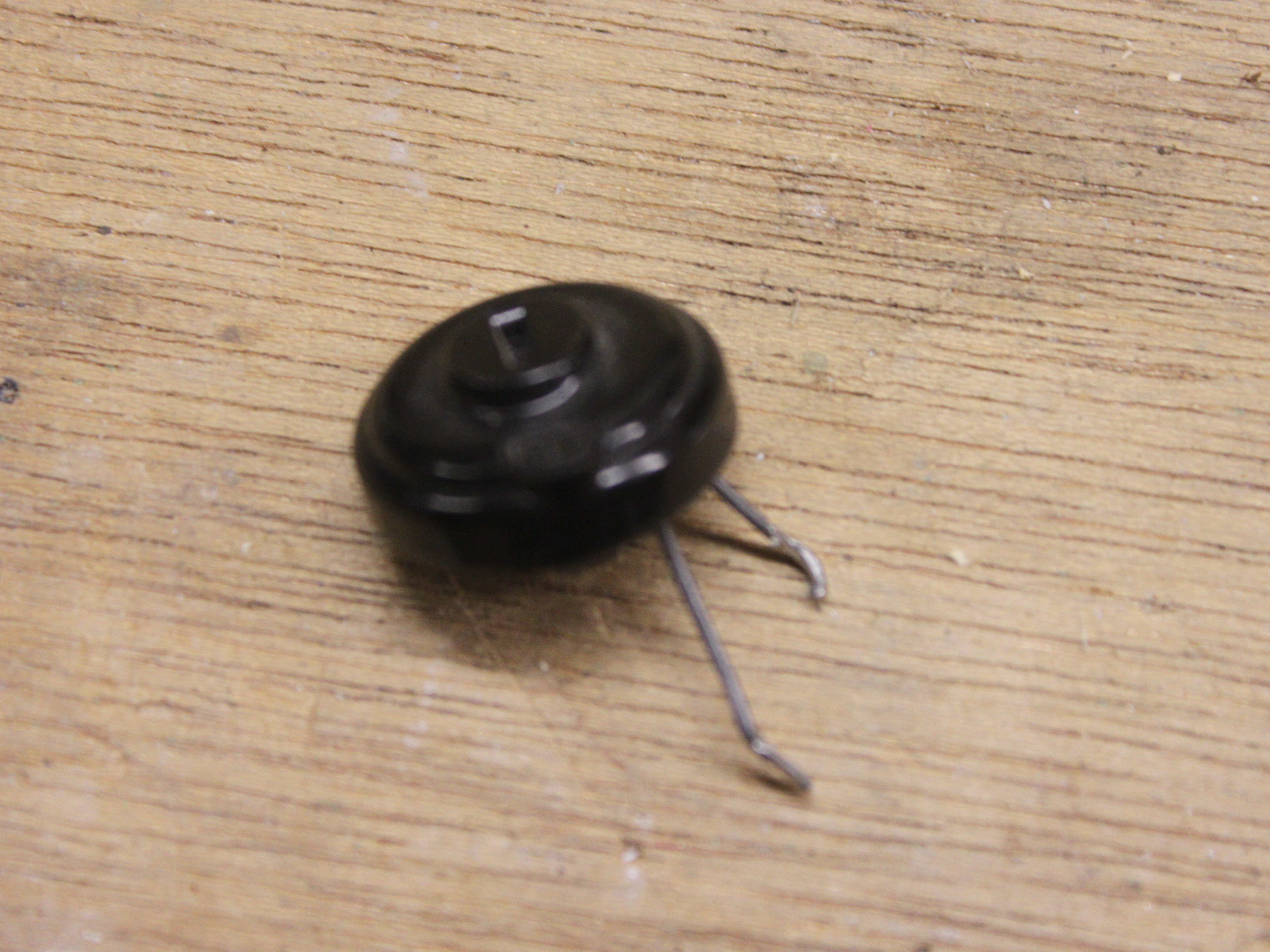
Find four matching potentiometers. I recommend ones that have a large flat surface so you can easily glue them to the arm pieces.
Most potentiometers should output values of 0 to 1023. If you find your arms to be not very responsive to your movements check what the potentiometers values are using the serial monitor. I found that the range of the potentiometers I used was from 21 to 589 so I had to map my values differently.
Wire your potentiometers to the breadboard. I had all the positive and negative leads going to one power rails. The signal wires should go to the analog inputs. Write down or remember which is which if you want to save time when doing the code.
If you find the servo moves the wrong way, try reversing the polarity of the potentiometer

Designing and cutting the arms.
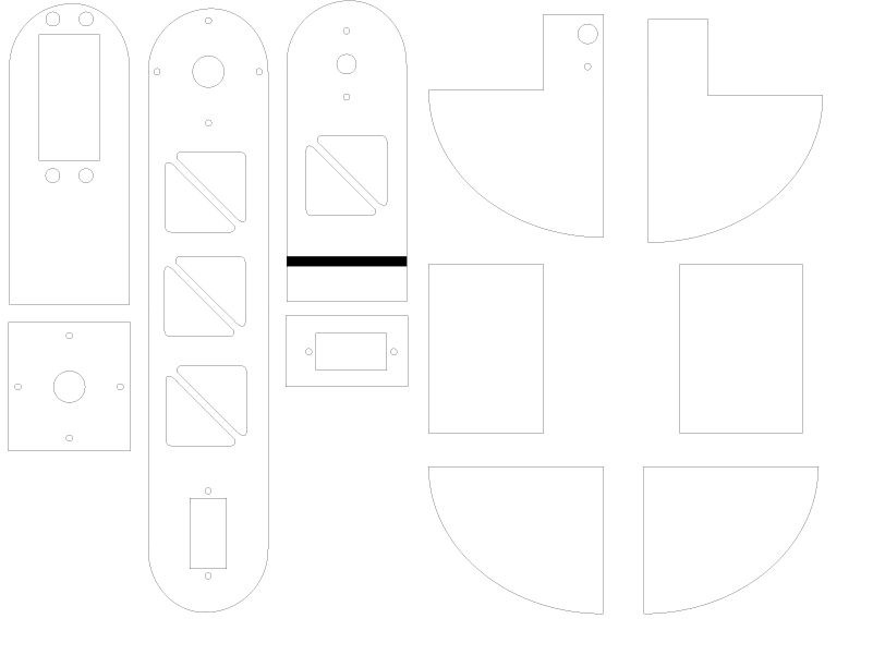
Using calipers, measure out where the mounting holes should be for your servos. I also rastered in circles for potentiometer placement and a line for gluing on the bracket for the claw.
The bracket for the claw is precisely positioned so the edges of the claw line up due to the thickness of the servo mount or the potentiometer mount
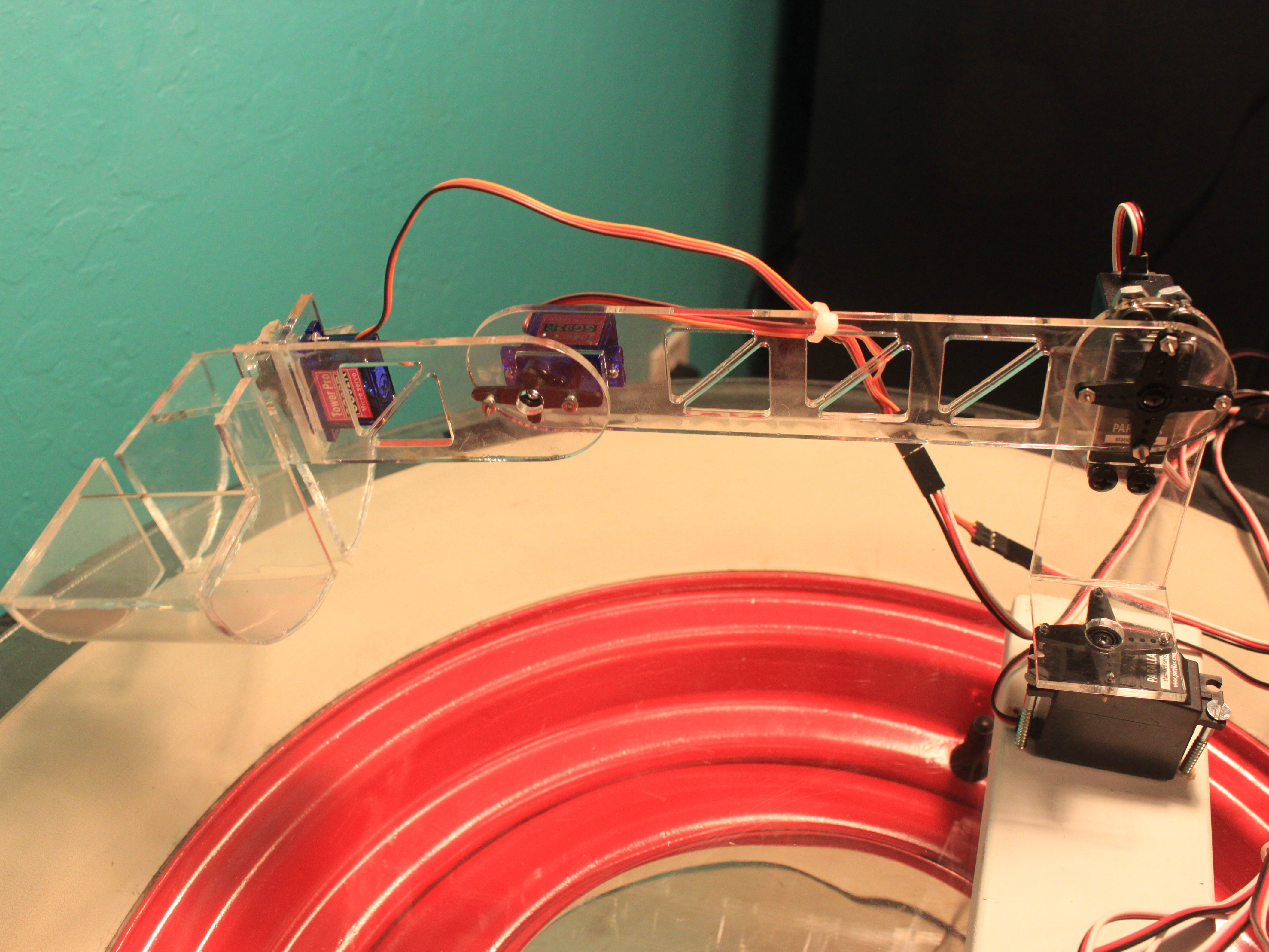
I also put in cut outs to reduce weight. I would be very considerate of the weight of the arm because I found that the servo that lifts the large arm segment barely had enough torque to lift the arm
After the arms are designed cut them using whatever methods are avaliable to you. I have access to a laser cutter so that is what I used.
Assembly
Now that you have all your pieces, it is time to assemble the arms. Keep track of which pieces are for which arm and assemble the arms like the pictures. I recommend doing any gluing first and then mounting servos and potentiometers.
I used a combination of hot glue and acrylic cement to assemble my arms. For lower joint that need a lot of strength I would use the acrylic cement.
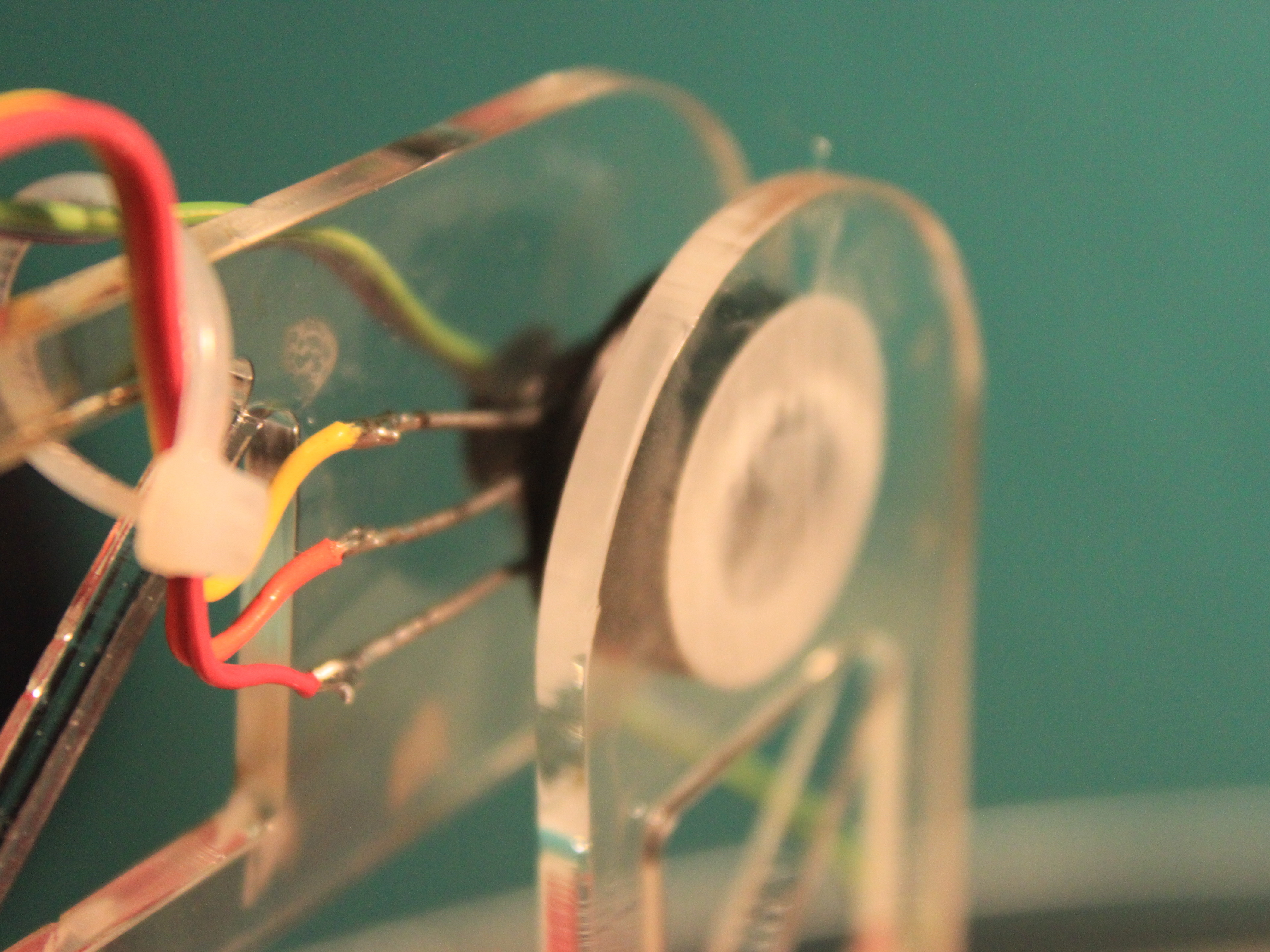
When mounting the potentiometers keep in mind their orientation. They need to be “facing” the same side or the servos will move opposite to your movements of the potentiometer arms
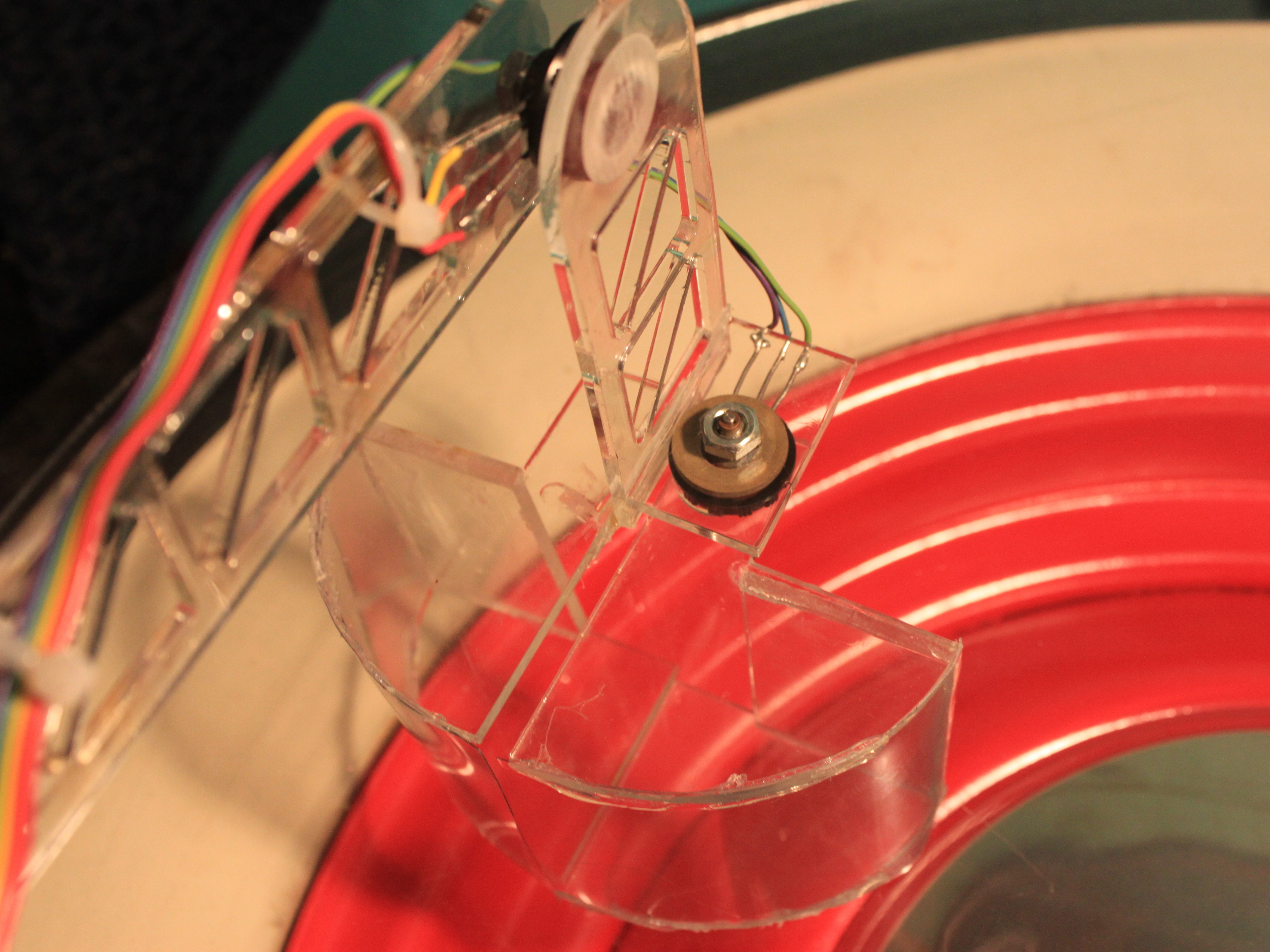
After I had the claw halves glued I cut out a piece of the very thin plastic to make the bottom. I found it easier to glue one end and cut to fit rather than measuring the curve for a dimension.
Wiring
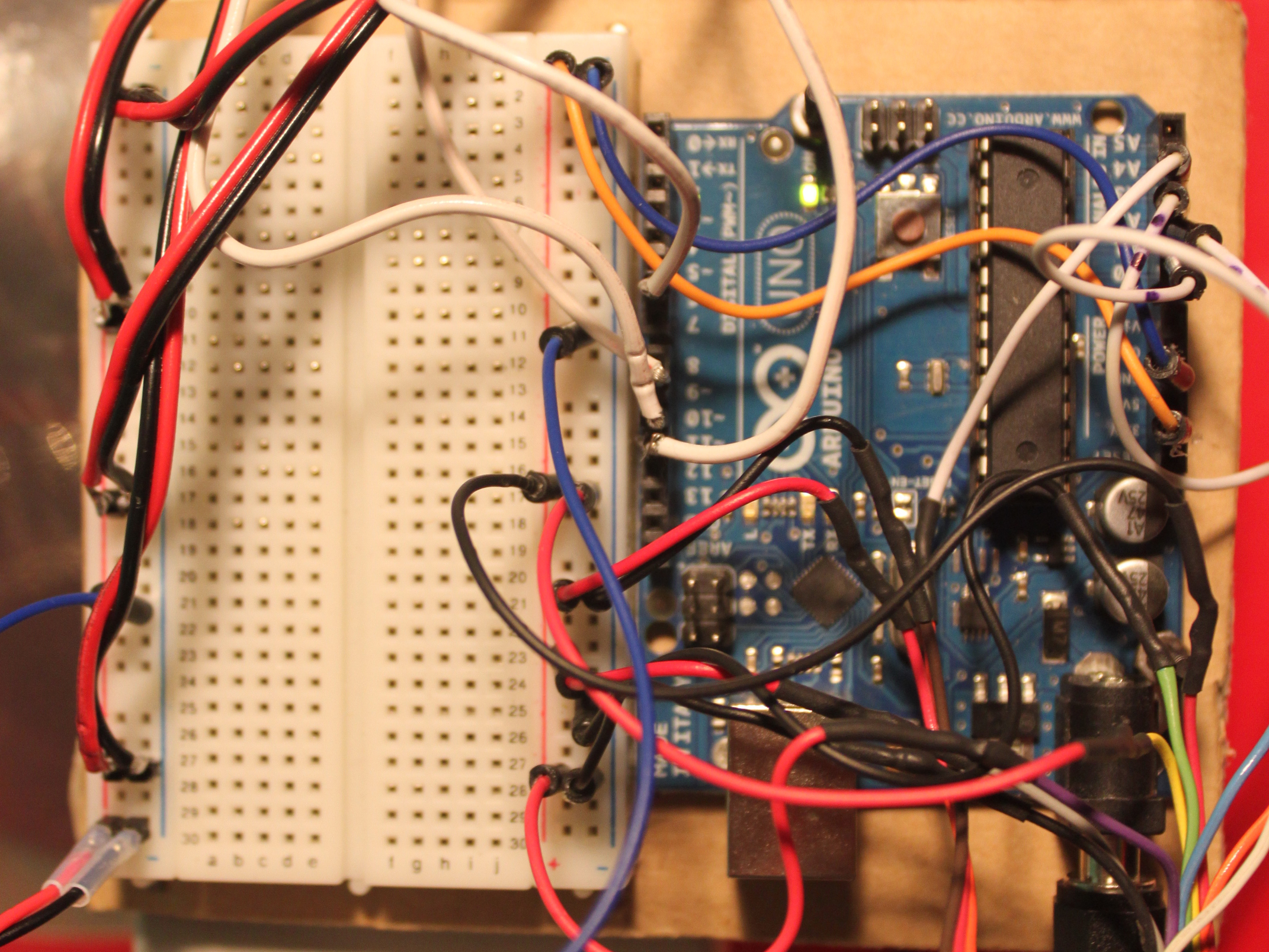
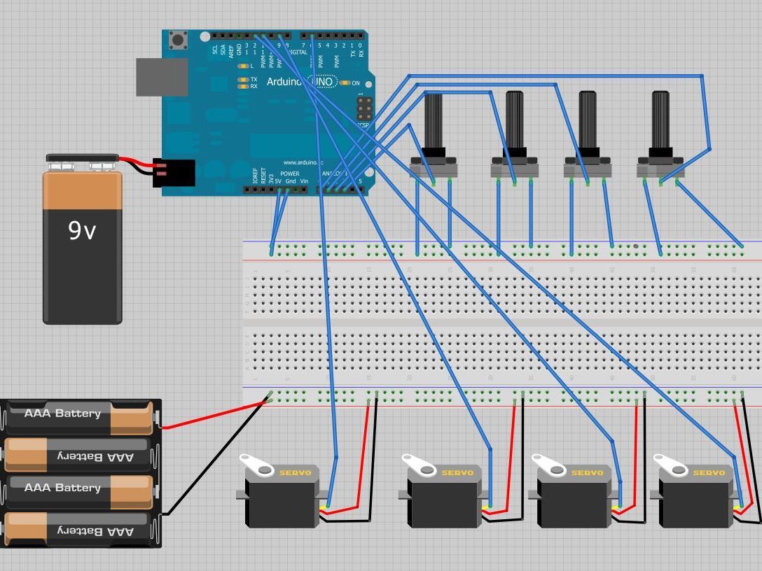
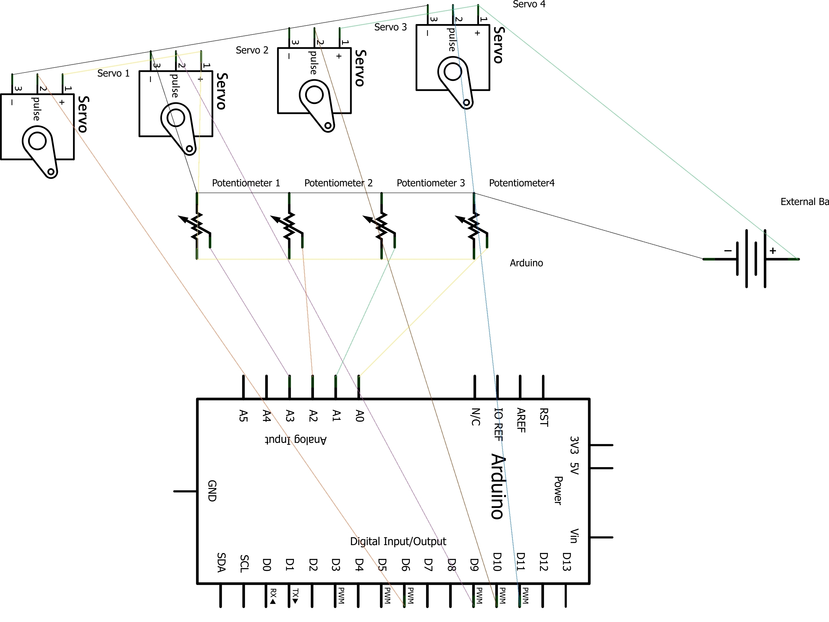
The wiring for this is not that complicated. Most of it is just distributing power and running signal wire
The positive and negative of the servos should go the power rail with the external battery pack
The positive and negative from the potentiometers should go to the other power rail on the breadboard
The +5 and Ground pins from the arduino should go to the power rail of the breadboard with the potentiometers
The signal wire from the servos should go to their corresponding digital output pin on the arduino (needs to be a pwm output)
The signal from the potentiometers should go to their corresponding analog input
I jumpered the ground of the power rail together to eliminate noise. I’m not sure if this is necessary for it to work, but it doesn’t hurt
The code
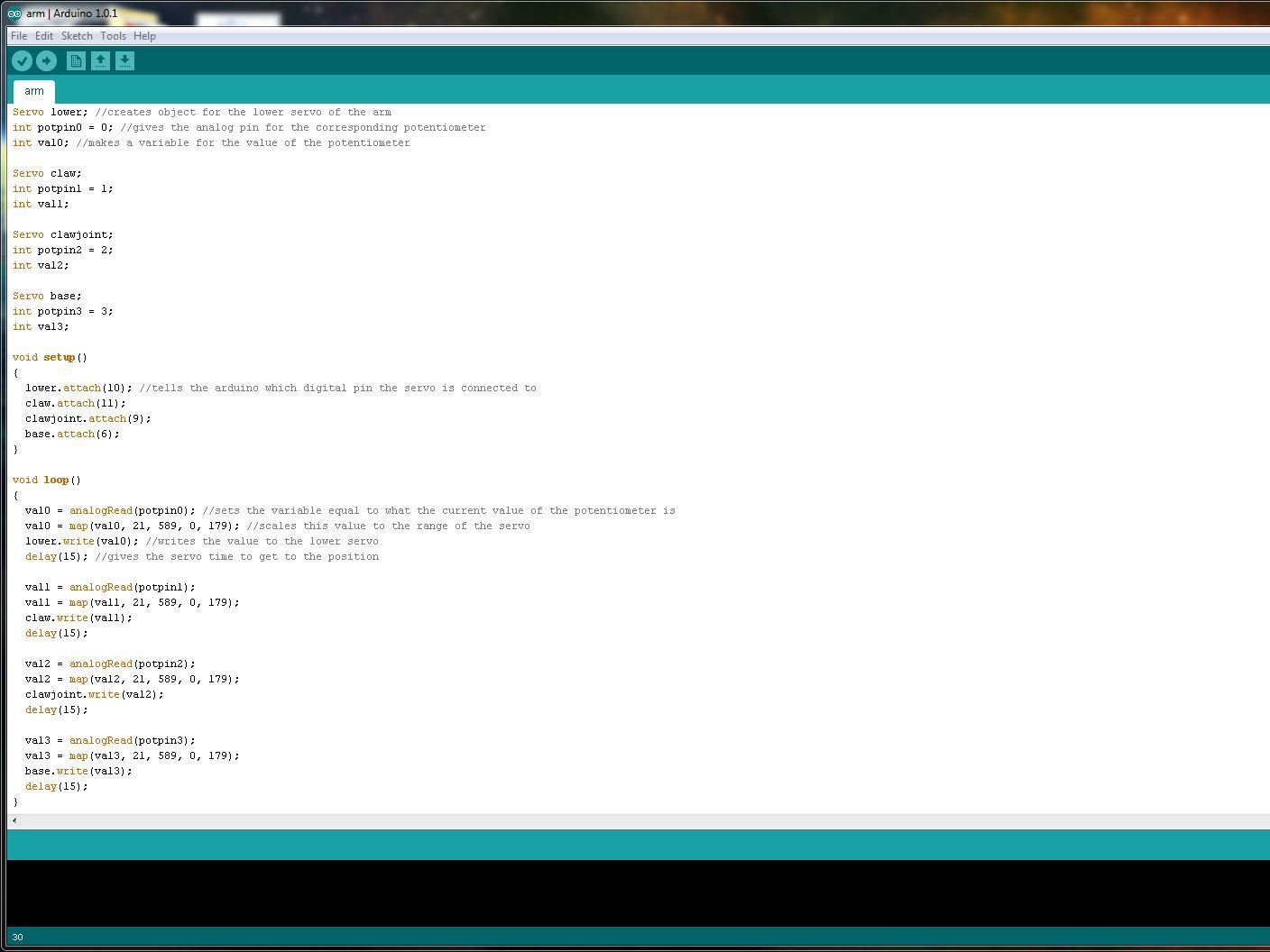
The code that I used to control the arms is very similar to the “servo knob” example that comes with all installations of arduino
Variables are made for each servo and potentiometer
The code reads the value of the potentiometer, maps it to the range of the servo and writes it to the servo in a loop.
See the attachments to this project for a pdf of the code where you can copy and paste it.
Other parts about this project that I would've liked to include but didn't have time to are adding code to make the servo arm move smoothly without twitching and using servos that have the ability to move a full rotation


