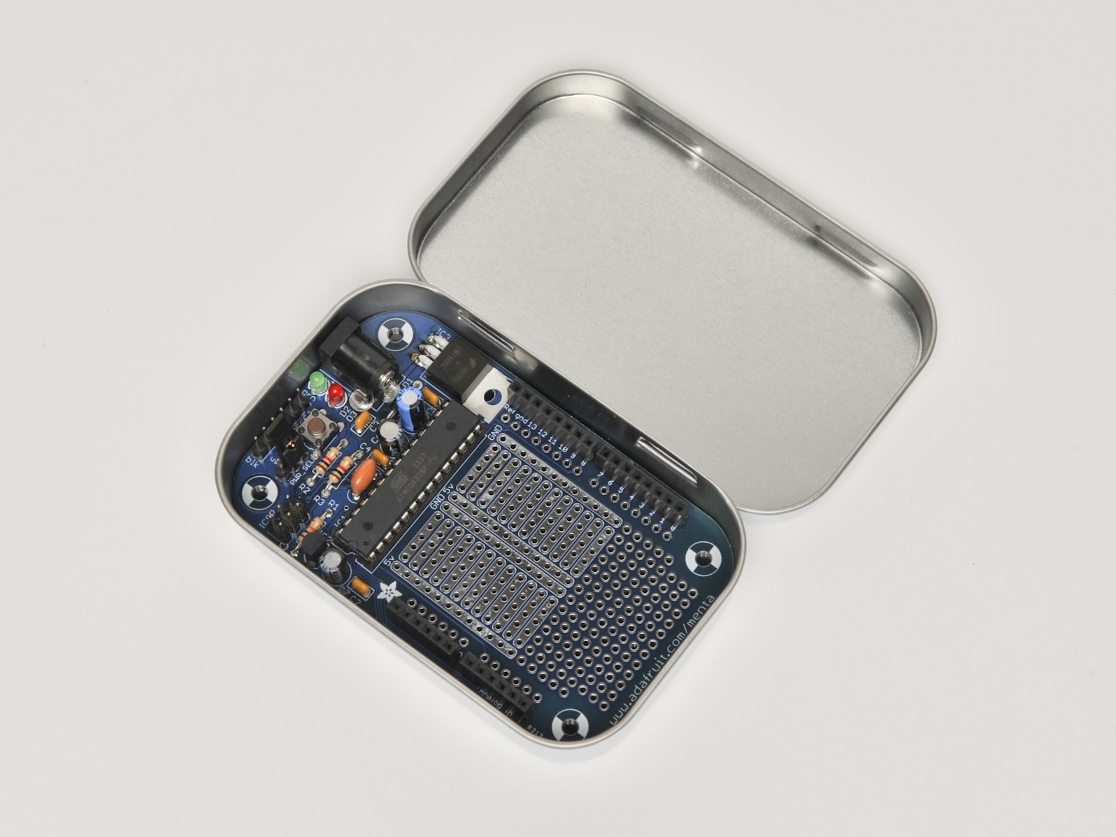
The Mintronics: Menta is a unique Arduino-compatible microcontroller kit. It features a handy, on-board prototyping space and is specifically designed to use the included mint tin as an enclosure! This makes it perfect for logging applications and on-the-go development. The prototyping area is perfectly sized for one of our mini breadboards (not included) so you can wire circuits without soldering. Ready for some expansion? The Menta can be used with all Arduino-compatible shields.

The Mintronics: Menta kit was designed in NYC by open source hardware pioneer Adafruit Industries, in partnership with MAKE and Maker Shed.

Note: Requires FTDI programmer (like the FTDI Friend) and soldering.

(Assembly photos and text are used with permission from Adafruit Industries)

Project Steps

Prepare to assemble!

Check the parts list and verify that you have everything. Then heat up your soldering iron and clear off your desk.

Place the circuit board in a vise or helping hands tool so you can easily work on it.

Place resistor R3.

Component R3 is a 1,000 ohm (1kΩ or 1K) resistor, indicated by brown, black, red, and gold stripes. Don’t confuse it with the 10K resistor which has an orange stripe. If you’re not sure, use a multimeter to check! This resistor sets the brightness of the red LED that’s used by the Arduino to indicate when it is bootloading (downloading sketches).

Bend the resistor into a “staple” shape and place it in the slot on the PCB marked R3, right over the resistor-shaped image. Resistors do not have polarity so no worries about putting it in backwards; they work the same either way.

Bend out the long metal leads so the resistor sits flat agains the board, and flip the PCB over.

Solder resistor R3.

Now we will solder in the first part. Heat up your soldering iron (about 700 degrees F is common but you may need to adjust it higher for lead-free) Using your soldering iron tip, press and heat both the pad (the silver ring around the hole) and lead (wire) at the same time for 2 or 3 seconds. Then poke the end of the wire into create a nice solder joint. Do this for both leads.

Using your diagonal cutters, cut off the long leads just above the solder joint.

Solder resistors R2 and R1.

R2 is another 1K resistor (brown black red gold) that’s used to set the brightness of the green LED, which indicates when the board is correctly powered. R1 is a 10K resistor (brown black orange gold) that’s part of the reset circuitry — it keeps the Arduino chip active when you want to, and helps reset it when the RESET button is pressed.

Bend and place them in the slots labeled R2 and R1.

Flip over the PCB and solder the 2 resistors.

Clip the 2 resistors’ leads.

Solder the ceramic capacitors.

Ceramic capacitors are used for high-frequency filtering and noise reduction. They’ll keep the power supply system stable even if you’re doing high-current stuff like motors, or really big LEDs.

The ceramic capacitors are yellow blobs; place them in locations C1, C2, C3, and C4. Like resistors, they’re not polarized, so they can be inserted either way and will work fine. Bend out the leads to keep them flat against the PCB.

Solder all the capacitor leads and clip them short.

Solder the reset button.

The RESET pushbutton is what you’ll press to reset the Menta, say if you want to start the program over.

Buttons are symmetric, and they only fit the holes one way, so just press it into place and it should snap in.

Solder all 4 legs of the button. There’s no need to clip them as they’re already quite short.

Solder the power diode.

Now you’ll place the first nonsymmetric component, a diode! The diode conducts current in one direction only, so we use it for protecting the Menta — it makes sure we don’t connect negative voltages into the DC plug that could damage or destroy the electronics. This diode is a 1N4001 model, an extremely common power diode that can handle over 1 amp of current.

Diodes have a stripe to indicate the cathode — this one has a silver stripe. Make sure the silver stripe matches the little white stripe on the PCB (in this image, it’s on the right-hand side). Double-check that you get this right because otherwise nothing will work!

Solder in the diode and clip the leads.

Solder the 5V voltage regulator.

This component takes a high voltage (from 7V DC to 25V DC) and regulates it down to 5V. The Menta circuitry requires a nice clean 5V DC to run; any more could burn it up. This regulator is the very common 7805 type in a big package that can handle up to 1 amp of current.

Place it flat on its back so it matches up close to the image on the PCB, making sure you can read the part number on top. Don’t worry if it doesn’t line up perfectly; you won’t use the hole in the regulator for anything (it can be used for heat sinks but it’s not necessary here).

Solder in the 3 legs and clip them short.

Solder the electrolytic capacitors.

These are the beefy versions of the ceramic capacitors we already placed. Ceramics are good for high-frequency noise, and electrolytics are good for low-frequency noise; that’s why we team them up together to cover all frequencies.

Electrolytic capacitors are polarized — they must be put in the correct way or they will be damaged so be super careful here. Capacitors have one leg that’s longer than the other, this is the positive lead. Place the positive lead in the hole marked with a tiny + next to it. See the images of how to place the 3 capacitors. C5 is a 25V 47uF cap (it’s bigger than the others) for filtering the incoming power from the DC power jack. C6 and C7 are smaller 6.3V 100uF for filtering the 5V and 3.3V supplies.

After you’ve triple-checked the polarity of the capacitors, flip over the PCB, solder them in, and clip the leads.

Solder the LEDs.

The indicator LEDs are the Menta’s way of telling you what’s going on. LEDs are light-emitting diodes — which means that like the 1N4001 they have a polarity and won’t work if placed backwards. Like capacitors, the also have a longer wire that indicates the positive lead. Place this wire in the hole marked with a +.

First place the green LED; this is the power indicator LED. Then place the red LED; this is the “pin 13″/bootloading indicator LED.

Solder both LEDs in, and clip the leads.

Solder the power jack.

Now you can place the big power jack. This is how you’ll plug in a battery or power adapter.

The power adapter has big flat pins, so that it can pass a lot of current and also so that it will stay mechanically attached to the board. Use a lot of solder to fill in the big pads completely.

Solder the crystal X1.

The 16.00MHz crystal, X1, is what lets the Menta chip run at a brisk 16 million clocks per second.

This oscillator comes in an orange shape with 3 pins. Luckily, it’s symmetric, so just place it any way you like.

Bend the leads, flip over the PCB, solder it in, and clip the leads.

Prepare the male breakaway headers.

Now you’re at the toughest part of the kit. Luckily you’ve done so many parts so far, you should be pretty comfortable with the iron. The problem with headers is that the leads are so short you can’t bend them when flipping the PCB over, so you’ll need to use tape or playdough or tack to hold them in place for soldering.

Take the long stick of “breakaway” male header and break off one 6-pin and one 3-pin piece. Keep the rest for a future project; it’s handy stuff.

Solder the male headers.

Place the 6-pin piece into the spot next to the green LED. Make sure the short legs are sticking down into the PCB and the long legs are sticking up. This is the programming header, where you’ll connect an FTDI cable or FTDI Friend to reprogram the Menta.

Place the 3-pin piece below that, in the PWR_SEL spot. This is for selecting whether you want to power from the FTDI cable or from the DC jack.

Finally, find the 2×3 header and place it in the ICSP spot. This is where you can connect an AVR programmer such as a USBtinyISP, Dragon, etc. to program the AVR chip.

Use your favorite tape to hold the parts in place. Masking tape works better than cellotape, but use what you have.

Flip over the PCB, check that the headers are still in place, and solder all the short leads in. You won’t need to clip them because they’re very short already.

Test your 5V DC power.

Place the jumper onto the PWR_SEL header on the right-hand side, in the DC position — this indicates that you’ll be powering it via the big DC jack.

To test your 5V DC power, find a power adapter 7V DC or higher, with a 2.1mm jack and center-positive polarity (these are nearly standard), and plug it in. With the jumper in place, you should see the green LED light up. If not, something is wrong — either the LED is in backwards or your power supply isn’t working. Go back and check your work until you can figure out what happened.

Solder the 3.3V regulator and 28-pin IC socket.

Once you know the 5V power supply is working, you can solder in the 3.3V regulator. This will let you power the many 3.3V sensors and accessories out there, a nice little extra! The chip is the MCP1700-330 — you should be able to see this marking on its face. It can supply up to 250mA, plenty for nearly any device you’ll be using. Place the chip so that its flat face matches the flattened image on the PCB.

Next, place the 28-pin socket next to it. This socket is a mechanical “holder” for the ATmega328 chip that drives the Menta. We socket it for a few reasons: to protect the chip, to make it easier to replace in case of damage, and so that you don’t have to worry about accidentally soldering it in backwards. (If you mess up on the socket, it’s a lot easier to fix than if you do the same with the chip.)

The socket has a little half-moon notch on one end. Make sure this notch matches the notch marked on the PCB — it will help you align the chip later. If you get this wrong, don’t try to remove the socket, just keep going.

Solder in the 3.3V regulator and all 28 pins of the socket, and clip the regulator leads. The socket doesn’t need to be clipped.

Place the ATmega328 chip.

Now we can place the ATmega328 chip — the brains of the Menta. Chips come with their legs in an A shape, but we want them in more of an H shape. Pick the chip out of the antistatic foam and holding it by the ends, bend the leads against the table to flatten them parallel to each other. Once they’re straight, they’re easy to fit into the socket.

Make sure you fit the ATmega328 chip in the right way, as it’s symmetric. One end has a half-moon cut out of it — this should be on the left side in the photos, matching with the notch in the socket and the notch marked on the PCB.

Test the ATmega328 chip and crystal.

Now you can do a second test, to check whether the chip and crystal are working right. Plug in the board again to the DC power and press the Reset button. You should see the red LED flashing a few times. Every time you press the button it should flash again. Once you’re happy, remove the DC power and you can finish up.

Solder female headers for shields (optional).

This step is optional, but if you want to plug in shields, you’ll want to complete it. If you want a more compact Menta, skip it!

Like the Arduino, the Menta can accept “shields,” pluggable add-ons to increase its functionality. If you want this ability, grab the two 8-pin female headers and two 6-pin female headers and place them in the outer pins marked “Digital I/O” and “Analog I/O” — there are 2 sets of pins so be sure to use the OUTER ones!

If you have a shield handy, you can plug it in now to test the fit, and hold the female headers straight while you solder them in. Otherwise use tape, or if you’re dextrous, hold the header with one finger while soldering.

Add bumpers.

Finally, you can finish your kit by placing the 4 rubber bumpers over the mounting hole spots. These will keep the Menta off your desk to avoid scratching it or accidentally shorting it against a piece of wire.

You're done!

That’s it! You’re done! Now you can read the User Manual for details on how to upload your favorite Arduino sketches.

Conclusion

(Assembly photos and text are used with permission from Adafruit Industries)