Safely and effectively charge your USB-powered devices when you are away from your computer with this handy charger!

Please note: There have been reports that the Minty Boost has issues charging the iPhone 3GS.
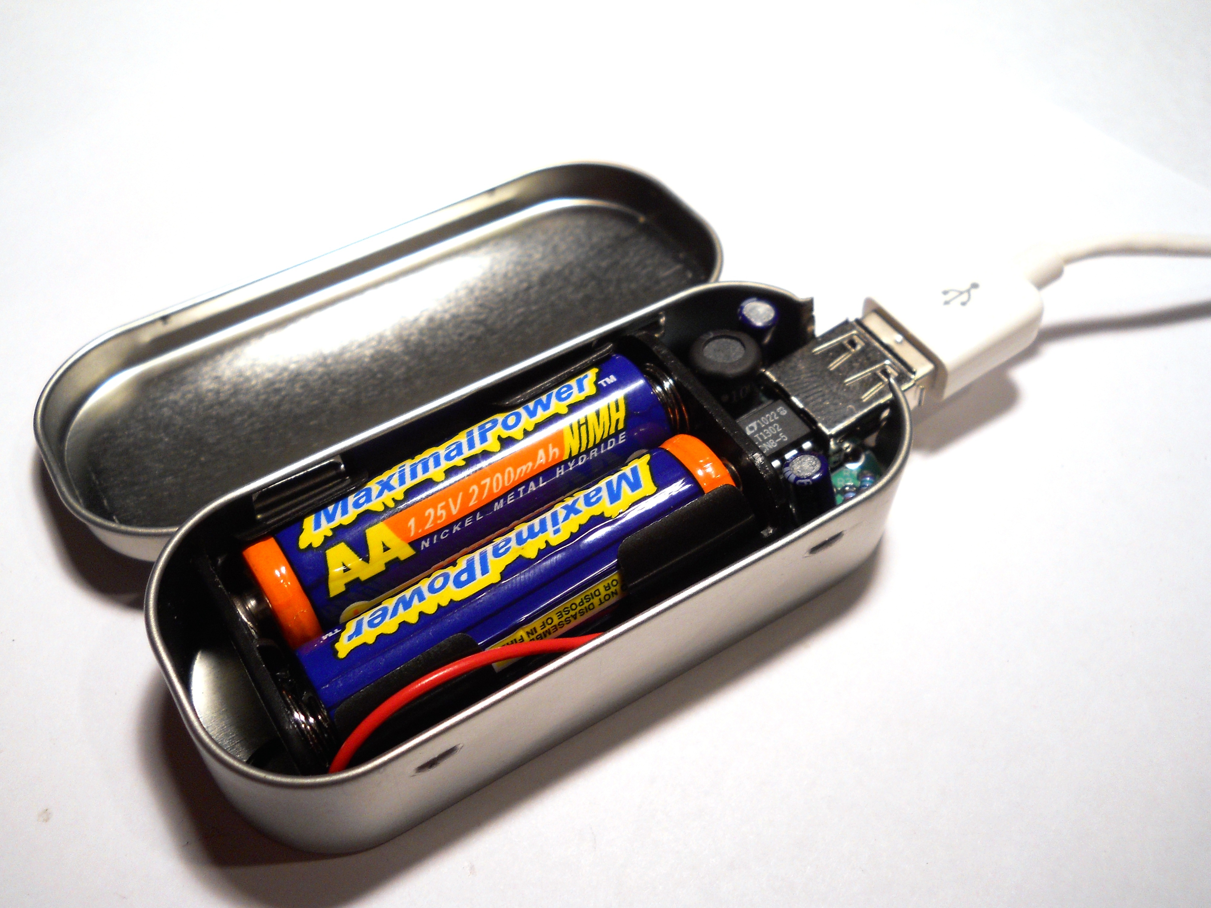
Project Steps

Gather your Materials

Check to make sure you have all of the necessary components to build version 3.0 of the Minty Boost.

Heat up your soldering iron and wet your sponge, and get ready to start!

Insert the 3.3K Resistor

In location R5, insert the resistor with color code Orange-Orange-Red.

Resistors are not polarized, so it does not matter which direction you insert it.

Solder it in, and then clip the leads.

Insert the 75K 1% Resistors

In locations R2 and R4, insert the blue resistors with color stripes of Violet-Green-Black-Red-Brown. Be sure to double-check the color code!

These are not polarized so it does not matter which direction you solder them in.

Solder the leads and then clip the leads.

Insert the Remaining Resistors

In locations R1 and R3, insert the resistors with color code Yellow-White-White-Red-Brown.

Solder them in and then clip the leads.

Insert the 0.1uF Ceramic Capacitors

In locations C1 and C2, insert the two yellow ceramic capacitors.

The direction of these components does not matter.

Solder them in and then clip the leads.

Insert the Schottky Diode

In location D1, insert the black component with the silver stripe.

Be sure to match up the silver stripe with the white stripe on the silk-screened image.

Solder it in and then clip the leads.

Insert the IC Socket

The IC socket goes over the 3.3K Resistor, but make sure that you match up the notch on the socket with the notch on the silk-screened image.

Be sure that the socket is flat on the PCB, and carefully solder the socket in.

Insert the Inductor

In location L1 insert the inductor. It does not matter in which direction you insert the component.

Solder it in and clip the leads.

Insert the Electrolytic Capacitors

In locations C3 and C4, insert the blue electrolytic capacitors.

These capacitors are polarized, so make sure that the longer lead of the capacitor is inserted into the hole marked with a “+” on the silk-screened image.

Solder them in and then clip the wires.

Solder in the Battery Holder

The red wire of the battery holder should be inserted into the hole marked with the “+”. The black wire should be inserted into the hole marked with the “-“.

Solder these wires in, and if necessary clip the leads.

Insert the Chip

With the notch on the chip matched up with the notch on the socket, press the chip into the socket.

Press it all the way into the socket to make sure it is secure.

First Test!

Begin by inserting two AA batteries into the battery holder. Either rechargeable or alkaline batteries will work.

Set your multimeter to read voltage, and place the red test lead on the leftmost pin and the black test lead on the rightmost pin.

The voltage reading should be between 5V and 5.2V. If not, then check to make sure your batteries are healthy (as well as the batteries in your multimeter).

Second Test

Now check between the rightmost pin and the second and third pin.

Your multimeter should measure around 2V.

Once everything checks out OK, remove the batteries and continue finishing the kit.

Insert the USB Type-A Connector

It should snap easily into place.

Solder the four middle pins first and then the two outside mechanical pins.

One More Test

Before you start assembling the enclosure, connect the charger to an iPod or other USB-powered device.

Make sure that your device begins to charge. Once you know that it is charging, you can build the enclosure.

NOTE: The chip will get very hot while charging. This is normal so don’t worry about it!

Making the Enclosure

Gather your empty Altoids gum tin.

Cut or Dremel two notches in the end of the tin around the area where the flat part ends and the tin starts to round out.

Bend this flap back and forth and break it off.

Into the Enclosure

Place the pieces of sticky tape on the bottom of the battery holder and on the bottom of the circuit board.

It is important that there is no contact between the circuit board and the metal enclosure. This would cause a short in the circuit.

Insert everything into the tin and then insert the batteries. Close the tin, and you are finished!

Conclusion

Adafruit has also documented the process of designing this kit, in case other people interested in designing and making kits are interested in learning how to start selling their own kits!