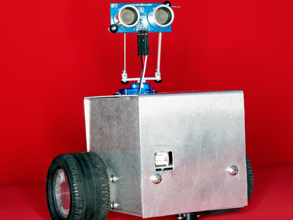
Makey is an autonomous robot that I’ve programmed to follow objects around and avoid obstacles. It has a fully enclosed chassis and uses tank steering, where separate DC motors power each of the 2 drive wheels.

Control comes from an Arduino microcontroller and a servomotor moves Makey’s head, which carries a single ultrasonic rangefinder. Makey constantly turns its head right and left to acquire differential ranging data, adding to its personality.

With different Arduino programming, the hardware would support mapping and other activities, and a few hardware mods would enable Makey to compete in Mini-Sumo, a popular event in robotics competitions.

Project Steps

Make the body.

The body consists of 2 pieces of sheet aluminum. You can cut, drill, and bend one piece at a time, or do both at once to minimize switching tool stations; see Step 5.

Download the 5 Makey templates and print them out full-size. Cut out the base cutting template, and cut holes in the blank area of each panel. Securely tape the template to the aluminum sheet with double-stick tape on the back and regular tape over the holes.

CAUTION: Always wear protective eyewear when cutting metal.

With a band saw, cut the aluminum roughly to size around the template, then cut the perimeter just outside the lines.

TIP: For inside corners, first cut a gradual curve close to the corner, then back up and cut into the corner’s point from each direction.

Use a center punch and small hammer to punch through the template at the 17 crosshairs (for drilling in the next step) and at the corners of the rectangles around the large holes.

Drill the holes at the crosshairs following the sizes marked on the template. Remove (but keep) the paper first, to line up on the punch marks more accurately.

Clamp the metal tightly onto scrap wood, and wherever possible use the unibit, which makes cleaner holes in thin metal than a twist drill.

For the starter holes inside the rectangles, you may need to adjust the diameter smaller or larger to reach the rectangle edges.

Finish the rectangular holes with the nibbler tool, cutting away until a rectangle appears. If you want, you can retape the template to see the rectangles more clearly. Then file the edges smooth.

Use a handheld deburring tool to remove burrs from the metal’s edges. To deburr the small holes, push the point of a larger drill bit over the holes and twist it by hand.

Cut out the base-bending template and attach it to the other side of the aluminum with double-stick tape, aligning the holes and rectangles.

Insert the metal in the brake with the new template facing up, and make all indicated bends at 90°.

First bend the tabs on each long side of the metal, then bend up the sides of the body.

For each bend, go up gradually, using a drafting square between small bends to check the angle.

For the body’s top cover, repeat Steps 1-4 using the top cutting and bending templates.

Now you’ve got one sweet chassis any robot would be proud to wear!

Add the drivetrain.

Mount the drive motors in the base using 4-40 x 1″ screws through the small holes. The motor shafts should poke out of the larger holes.

Secure the screws with lock washers and nuts on the motor side. The base is small, so you may need needlenose pliers for tightening.

Use a 2″ hole saw in a drill press to cut wheels out of some scrap wood. I used 1×8 shelving and my finished wheels were 3/4″ thick by about 1.8″ in diameter. Clamp the wood, and go slowly to avoid stalling the drill press.

Center a wheel hub on each wooden wheel and use a small nail to mark 2 of the hole locations. Drill through the locations with a 1/8″ drill.

Paint the wheels. I love the Rust-Oleum red gloss; it is super thick, brightly colored, covers great, and cleans up easily. Try not to get too much paint in the mounting holes.

Drill through 2 opposing holes in the hub with a #43 drill, then use a 4-40 tap to create threads in each hole.

Use two 4-40 x 1″ screws to attach the wheels to the hubs from the outside. Don’t overtighten.

Install tires on the wheels, orienting them with the larger diameter facing out. Then snap each wheel assembly into its motor shaft.

Attach the skidder to the bottom of the base using the screws, nuts, and the thinner of the 2 spacers it comes with.

Add the power and control.

Cut a plate out of hard plastic following the mounting plate template printed in Step 1. Punch and drill it as indicated, then test-fit the plate into the robot body, resting on the motors, and file as needed for a snug fit.

Use two 4-40 x 3/8″ screws to fasten the Arduino board to the plate from the underside, securing it with nuts on top. The USB connector should line up with the notch in the tab.

Pop-rivet the battery holders into the body through the holes in the left side tabs. Rivet from the outside so the ugly side of the rivet faces the battery.

Solder together the ProtoShield following the manufacturer’s instructions, linked at ProtoShield Assembly and Use.

Use the band saw to slice off the board’s BlueSMiRF header, which connects to Bluetooth wireless modules. Wasn’t that fun? The header won’t fit in the robot and we don’t use it.

Stick the mini breadboard onto the ProtoShield and plug the ProtoShield onto the Arduino. If you are using a Diecimila, set its power jumper to EXT.

Add the sensor and servo.

This project uses the shorter of the 2-arm horns that come with the HS-55 servo. Use a 1/16″ bit to drill out the outermost holes in this horn.

Press-fit the metal pieces of the 2 Du-Bro Mini E/Z Connectors into the servo horn holes from the front, and secure them in back with the black rubber pieces.

Thread the control rods from the Du-Bro Aileron System through the connectors and screw them down using the included screws.

Here’s a tricky part. Plug the servo extension wire into the Ping sensor board. Bend the control rods from the horn in opposite directions 90°, to reach mounting holes at opposite corners of the board.

The rods will point up from the servo, allowing room for the extension plug, and the sensor should face out. Slip the pushrod housing that came in the Du-Bro package over the rods to avoid short-circuiting the sensor, then secure the rods to the board using the connectors from the aileron control kit.

Slip the pushrod housing that came in the Du-Bro package over the rods to avoid short-circuiting the sensor, then secure the rods to the board using the connectors from the aileron control kit.

Thread the wires from the servo and sensor down through the rectangular cutout in the body’s top piece.

Fit the servo in the cutout, and fasten using two 1-72 x 1/4″ screws and nuts through the holes on either side. Clip the excess control rod length.

Screw the horn onto the servo and use a small screwdriver to adjust it so that Makey’s eyes face forward.

Connect and test the drive motors.

The contact tabs on our inexpensive motors are fragile, so their connections must be strong and vibration-proof.

Remove the motors and Arduino board from the robot body.

Cut 2 red and 2 black 12″ leads out of the stranded wire and strip 1″ off an end of each. Without soldering, wrap each red/black pair around the round back end of the motor (for strain relief), then run the wires along the top and stick them on with a sandwich of double-stick foam tape. Don’t cover any of the holes in the motor body, and leave room for the mounting nuts.

Thread and solder the capacitor leads through the holes in each motor’s connector tabs. This requires innovative bending with needlenose pliers. Then solder the motor wires to the capacitor leads, not the motor connectors, making a strong joint. Clip the extra lead length. Then cover the capacitor and the wrapped-around wires with black tape, and use more foam tape to cover the pointy bits.

Twist the free ends of the motor wire pairs together; this also reduces noise on the circuit. Mark the motors as Left and Right.

Solder and heat-shrink short solid-core jumper wires to the drive motor and battery snap leads (this lets you plug them into the breadboard). Route the motor wires through the big holes in the plastic mounting plate.

Plug the motor driver over the central trench of the breadboard and wire it to the drive motors and one battery, following the schematic. (Recall that on each side of the trench, holes in the same row are connected.) Use short jumpers to keep the wires close to the breadboard, as big loopy wires won’t fit inside the robot.

Download and install the Arduino software from arduino.cc. Hook the Arduino to your computer via USB, and if it’s a Diecimila, move its power jumper to “USB.”

To test the motors, run the program 01_Test_Motor_Rotation. The left motor should run forward and back, followed by the right motor. If not, check your wiring. Next, run 02_Test_Motor_Speed. The motors should start slow, speed up, and then reverse direction. Otherwise check wiring to pins D11 and D3.

Connect and test the servo and sensor.

Replace the motors and Arduino assembly in the robot body. Plug a 3-pin right-angle header into the breadboard, plug the servomotor cable into it, and wire the servo: black to GND, red to +5V, and yellow to Arduino pin D10.

Plug the other 3-pin header into the breadboard, then plug in and wire the rangefinder: black to GND, red to +5V, and white to Arduino pin D9.

Run the program 03_Test_Servo_Center, which centers the servo, then unscrew and realign the servo horn as close to center as possible. You can’t get it exactly in the middle, because the teeth on the shaft won’t allow it, but we can nudge it later.

Run <a href="http://cdn.makezine.com/make/19/04_Test_Servo_Sweep.pde" target="_blank"04_Test_Servo_Sweep, which should make the servo slowly rotate from one side to another.

To test the sonar rangefinder, run <a href="http://cdn.makezine.com/make/19/05_Test_Sensor_Distance.pde" target="_blank"05_Test_Sensor_Distance and then click on the serial monitor icon in the Arduino software. You should see distance readings spitting out, and if you move your hand in front of the sensor, the readings should change. If your readings are stuck at 0cm or 255cm or otherwise incorrect, check your wiring, and make sure the sensor isn’t plugged in backward.

Now we can connect the Arduino power. Unpack the Arduino one last time. To add the on/off switch, solder the unused battery snap’s red wire to one side of the switch and a solid red wire to the other. Also solder a solid black wire to the battery’s black wire.

Thread the wires out through the rectangular hole in the side of the robot body, and then press in the switch. Orient the switch with the “1” label at the top and fit it through the hole. It’s a tight fit and you may need pliers.

Wire the red lead from the switch to the RAW pin on the ProtoShield (which connects to Vin on the Arduino) and the black lead from the battery snap to the ProtoShield’s GND pin. If you’re using the Diecimila, move its Power jumper back to EXT.

Button it up.

Now that all your electronics are working, carefully put everything back into the body without knocking loose any wires. Install the batteries and prop the robot up on something so it doesn’t run off the table. The USB programming jack should line up with the cutout in the body.

Reload and run the test program 01_Test_Motor_Rotation, noting that the front of the robot is where the USB jack and skidder are. If the motors rotate the wrong way, check your wiring to pins AOut1, AOut2, BOut1, BOut2, AIn1, AIn2, BIn1, and BIn2. You may also need to reverse the motor connections.

Rerun the other test programs to make sure all the wiring is still OK. When satisfied, fold up the servo and sensor wires and tuck them into the base. Slide the top cover on, and install 4 sheet metal screws to hold it on. You’re done!

Robot Programming

Sometimes when you’re done building, you’re done building — but you’re never done programming. This is where you get to be creative.

In the code, you control the motors by using the digitalWrite and analogWrite functions to pass values to pins on the motor driver, 3 for each motor. One pin takes a number 0–255 and sets the current sent to the motor, which determines its speed. The other 2 pins take binary values that set each motor contact to either high or low voltage. This sets the motor’s direction (when only one contact is high):

void Forward()

You can write similar routines for the more basic motions, such as Backward (both motors backward), Spin_Left (right wheel forward, left wheel back), Arc_Left (right wheel forward, left wheel stopped), and so on. The Arduino programming environment makes it easy to experiment with code and load new programs to your robot.

Another fun behavior is object avoidance, which runs the loop: Move forward a bit, then take a distance reading. If the object is too close, take evasive action, such as back up and turn. Repeat.

Robot Mini-Sumo

In a Mini-Sumo match, 2 autonomous robots are placed in a ring painted black with a white border.

With narrower wheels, like the GM Series plastic wheels from Solarbotics, Makey would fit within the maximum size and weight allowable for Mini-Sumo: a 10cm-square footprint and 500 grams. You would probably need another sensor pointed down to see the ring, but the Arduino has room for several more inputs.

Resources

For more information about robot programming and behavior, I recommend Robotics with the Boe-Bot from Parallax, Inc. (http://parallax.com).

Advanced Programs