YouTube player

MAKE contributing editor Charles Platt proposed a “Hypothetical Tremolo Wheel” in his article about online DIY guitar stomp-box communities (MAKE Volume 15, page 82, “Stomp Box Basics: Tremolo and Fuzz”).

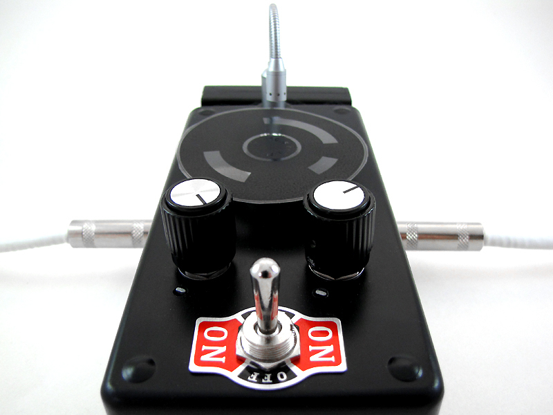
Well, it’s hypothetical no more. I took Charles’ cue and built this Optical Tremolo Box, which reads a patterned disk with a light sensor to create a warbling volume effect (tremolo) that you can custom-program with any pattern you like.

How does tremolo work? So there’s your electric guitar, and there’s the amplifier it’s plugged into, and there’s the cable that runs between them. Open up that cable and you’ll find 2 wires — one “ground” and one held at a positive voltage relative to “ground.” The changing electrical potential between these 2 wires, over time, is what carries the sound signal.

What happens if you short-circuit those wires, bridging them with a third wire? The sound goes away. The charge can find its way home now, via the short, without ever bothering to go all the way through your amplifier. And so it does.

What if you bridge the 2 wires with a resistor instead? With a strong resistor, nothing happens — it’s still easier for the charge to go through the amp. With a really weak resistor, the sound cuts out. With a resistor in the middle range, the sound will be quieted, but not completely muted, as the charge divides itself between short and signal pathways. Use a variable resistor, and you have a crude volume control: turn the resistance way up, the sound will be loud; turn it way down, the sound will vanish.

And here’s where Charles had a clever idea: use a resistor that responds to light. Wave your hand in front of the photoresistor, and the volume will respond to the shadow of your hand. Mount a spinning disk with alternating clear and opaque bands in front of it, and the volume will follow the pattern on the disk, repeating as it spins. That’s tremolo — a repeating variation in volume over time.

Intrigued? Want to try building one? I thought you might. Let’s get started.

MAKE Volume 33 features our special Software for Makers section covering apps for circuit board design, 3D design and printing, microcontrollers, and programming for kids. Also, meet our new Arduino-powered Rovera robot and get started with Raspberry Pi. As usual, you’ll also find fascinating makers inside, like the maniacs on our cover, the hackers behind the popular Power Racing Series events at Maker Faire.

Try your hand at 22 great DIY projects, like the Optical Tremolo guitar effects box, "Panjolele" cake-pan ukelele, Wii Nunchuk Mouse, CNC joinery tricks, treat-dispensing cat scratching post, laser-cut flexing wooden books, sake brewing, growing incredibly hot “ghost chili” peppers, and much more.

On newsstands now, by subscription, or available in the Maker Shed

Buy now!

Project Steps

Drill the enclosure.

Download the drilling template (PDF) and print it out onto a full page adhesive-backed mailing label.

Cut out the 4 template sections, peel off the backing, and affix them to the front, top, and sides of the enclosure box.

Drill the holes where marked. Start each hole with a 1/8″ brad-point bit, then switch to a unibit to drill the bigger holes out to finish diameter.

Peel off the templates and discard. A bit of rubbing alcohol can help if they don’t come away cleanly.

Mount the rheostat.

This knob controls the motor speed. First, bend all 3 contacts on the rheostat down 90° so they’re parallel to the shaft. Then turn the rheostat all the way “down” (counterclockwise).

We add a 15Ω resistor, in series, to bias the range toward the slower speeds, which are more useful for tremolo effects. Solder one lead of the resistor to the rheostat center contact and the other to a 3″ length of wire.

Use your multimeter to check the resistance between the center wire and each of the other 2 rheostat contacts. One of them should read about 15Ω and the other about 40Ω. Solder a 4″ length of wire to the 40Ω contact.

Cover the resistor and all soldered connections with heat-shrink tubing. Shrink it in place with a candle or cigarette lighter flame.

Remove the nut and washer from the rheostat, and insert it through the hole in the enclosure from inside. Fit the indexing tab into the alignment hole, put the washer over the shaft, and gently but firmly tighten the nut with a 12mm wrench.

Fit the knob onto the shaft and secure it in place by tightening the setscrew with a small flat-blade driver.

Mount the audio pot.

This knob controls the intensity of the tremolo effect. First, cut the shaft to the same length as the rheostat using a hacksaw. Then turn the pot all the way “down” (counterclockwise) and file a small flat surface on the side directly opposite the indexing tab. This will ensure that the the shaft always turns with the knob.

Again, identify the pot’s “high” contact using the resistance setting on your multimeter. Solder a 4″ length of wire to this contact.

Now, bend the remaining two contacts towards each other until they overlap, then solder them, together, to a second 4″ length of wire.

Mount the pot in the enclosure, with its indexing tab in the alignment hole. Secure the shaft in place with its bundled flat washer and nut. This one takes an 11mm wrench.

Add the photoresistor.

These cadmium sulfide (CdS) photoresistors come in packs of 5 with big, medium, and small sizes. We’ll use one of the medium-sized resistors and an LED holder to mount it.

Remove the rubber insert from the LED holder. Guide the legs of the photoresistor through the holes in the insert until the resistor body is seated against the insert.

Cut two 4″ lengths of green wire. Strip about 3/4″ of the insulation off each end, twist the copper strands together tightly, and tin one end. Solder the tinned ends to the photoresistor leads.

Slip a piece of 2mm heat-shrink tubing over each wire so it completely covers the solder joints and exposed photoresistor leads. Shrink it in place.

Push the insert back into the LED holder until the photoresistor is seated in the opening, as shown. Put the LED holder through the enclosure panel from the front, and tighten down the hex nut and split washer from behind using a 10mm wrench.

Mount the motor.

The hub we’re using to mount the sweep disks has a 3mm arbor hole, but our motor’s shaft is only 2mm across. A short section of ink tube from a ballpoint pen makes a perfect adapter. Just push the shaft of the motor into the tube and cut off the excess with a sharp hobby knife.

Solder a 3″ length of wire to each of the motor’s contacts.

Pass the motor shaft through the hole in the enclosure from the inside, then secure the motor in place with a #4×1/4″ wood screw in each of the 2 mounting holes.

Don’t overtighten the screws, or you risk stripping out the metal in the motor casing.

Mount the switch.

Strip about 1″ of insulation from one end of each of six 4″ wires. Though the colors don’t really matter, it’s helpful to have 3 wires in each of 2 colors. I used red and black.

Tin the stripped end of each wire and wrap it around one of the 6 screw terminals on the switch. Give the wire a twist or two, tighten down the screw, and insulate the connection with heat-shrink tubing. One row of 3 contacts on the switch should be all “red” and the other 3 all “black,” as shown.

To keep the switch from rotating in its mounting hole, apply 2 small pads of double-stick foam tape to the top — one on each side of the handle.

Peel the backing off the tape and insert the switch into the mounting hole from inside the enclosure. Align it as shown, then press the tape into place. Slip the label plate over the threaded shaft and then add the panel nut. Tighten gently with a 14mm wrench.

Add the power and phono jacks.

Attach 4″ leads to the DC power jack and each of the 2 phono jacks. In each case, ground (black) goes to the outer or “case” contact. Solder and insulate the connections with heat-shrink tubing.

Insert the DC power jack through the mounting hole in the top panel, from outside the enclosure, and secure it inside with the bundled washer and panel nut. Tighten gently with a 14mm wrench.

Insert one of the phono jacks through one of the mounting holes in the side panel, from inside the enclosure, and secure outside with the bundled washer and panel nut. Repeat for the other jack. Tighten gently with a 12mm wrench.

Install the Flex-Light.

Remove the D-ring from the end of the Micro Flex-Light by using a pair of needle-nose pliers “in reverse”: close the jaws, insert the nose into the ring, and then gently pull the handles apart to pry the ring open. Discard the ring or save it for another project.

Slide the lapel clip fitting off the end of the lamp body. Discard the clip or save it for another project.

Fit the rubber grommet into the center-top hole in the front panel. It’s easy; just squish it in until the lip of the hole is cleanly engaged with the groove in the grommet. A small flat-blade screwdriver may help with lifting and pushing the rubber, here and there, to get it just right.

Insert the bottom of the Micro Flex-Light into the grommet from above and push it into the enclosure. This will take a bit of force, but not much, and will hold the Flex-Light securely in place. You can adjust it up and down, or left and right, or take it out completely, for instance to replace the batteries.

Wiring and assembly.

Wire up the circuits using an 8-position terminal strip, as shown, cutting the leads to length and stripping the ends as you go. These “European” style terminal strips are nice because all you have to do to make a connection is insert the stripped wire end and tighten the screw.

The circuit diagram is also available for download as a printable PDF.

For ease of access and assembly, the terminal strip is not mounted to the enclosure, and just hangs freely. By the time all 16 connections are made, it is quite secure and will not wobble around.

Put the plastic bottom of the enclosure in place and secure it with the 4 bundled screws.

Attach adhesive feet. TIP: Three feet are less likely to wobble, on an uneven surface, than 4.

Power it up.

To run the motor, 3V DC is supplied through the power jack, which takes a size M plug. You can use a 3V “wall wart” to run the unit from mains power.

You can also build a simple battery pack with a ready-made 2×AA battery holder, a size M coaxial plug, and a bit of heat-shrink tubing. Attach it to the outside of the enclosure with peel-and-stick hook-and-loop fasteners (aka velcro).

Make the sweep disks.

Download the sweep disk art (PDF) and print it onto an 8.5″×11″ transparency. If you want to design your own disk art, an editable SVG version of this file is available at makezine.com/go/tremolodisks.

TIP: If you’re using a laser printer, you may notice that the printed transparency acquires a slight curl from the heat. To flatten it, simply flip the printed film over and “print” a blank page on the opposite side.

Cut out each disk using sharp scissors. Then apply a 5/8″ diameter velcro “dot” to the center of each disk. Use the softer, “loop” velcro on the sweep disks.

Apply a matching “hook” dot to the top of the aluminum mounting hub.

Slip the hub over the motor shaft. Make sure the hub is up enough along the shaft to clear the motor mounting screws when it rotates. Tighten the setscrew, using the Allen wrench that came with the hub, to secure it to the motor shaft.

Rock your Optical Tremolo Box.

Pick your favorite sweep disk and attach it to the hub by joining the velcro dots.

Plug your instrument or other sound source into one of the 2 phono jacks, and your amplifier or other sound receiver into the other. The tremolo circuit is symmetrical, so it doesn’t matter which plug goes into which jack.

Plug in the battery pack or wall wart. Turn on the LED Flex-Light, then flip the switch in either direction. One will cause the disk to turn clockwise, and the other will cause it to turn counterclockwise, which may vary the effect depending on the pattern on your sweep disk.

The knob on the right, above the switch, controls the motor rotation speed. At low positions, the motor may have a hard time getting started. Try turning the speed up a bit and then adjusting it back down to get the lower speeds.

The knob on the left controls the intensity of the tremolo effect. Turn it clockwise for more tremolo, counterclockwise for less. The brightness of the light on the photoresistor also affects the tremolo intensity, and though the high-intensity LED in the Micro Flex-Light provides plenty, you should experiment with other light sources. Especially the sun!

Conclusion

We've shown you how to make your own Optical Tremolo Box. Now show us how to make it better!

Here are a couple of ideas:

1) Printable transparencies are a super handy way to make the sweep disks, and they work well enough, but if you experiment a bit, you will probably find that the black areas on a printed transparency still let a bit of light through from the LED. Try covering the black parts of one of the disks with small pieces of electrical tape, which is truly opaque, and you'll be able to hear the difference: the tremolo effect gets stronger. What might be a better way to make the disks?

2) Wiring a potentiometer in series with a DC motor is a simple, cheap, and easy way to control the motor's speed, but it is not ideal. Especially at the low speeds that produce better tremolo effects, a series potentiometer is inefficient. We can get away with it because so little power is required to spin the disk, but the circuit could certainly be improved. What might be a better way to control the motor's speed?

We look forward to seeing what mods you come up with.