YouTube player

Summary

Build a super accurate, scaled 3D-model of a polypeptide chain that can be folded into all the basic protein structures, like α-helices, β-sheets, and β-turns. The model, called a Peppytide, is made by linking together many 3D-printed molecular subunits with a series of precisely placed magnets and screws. Once built, the Peppytide chain faithfully reproduces the size, shape and flexibility of proteins. When it is carefully folded into the protein helix and sheet structures, the model becomes locked in by all the magnets and becomes quite rigid.

Introduction

Proteins make up over half the dry weight of our cells. They are all built by the same amino acid units, linked together into long linear chains (called polypeptides). What makes each protein unique is the way these chains fold into precise 3D shapes. This folding process is quite complex and usually studied with the aid of computer graphics. But wouldn’t it be cool if you could hold these chains in hand, and actually fold them into real protein structures?
Here we demonstrate how to assemble a polypeptide chain model which you can hold and play with, and explore the protein structural motifs. The model is made from custom 3D-printed parts and some readily available parts. For the interested ones who want to explore the model in a greater detail, we have published a deeper scientific analysis of the model in a recent research article (Promita Chakraborty, Ronald N. Zuckermann. A coarse-grained, foldable, physical model of the polypeptide chain. Proc. Natl. Acad. Sci. U.S.A., vol. 110 (33) 13368-13373 (2013).).

Overview:

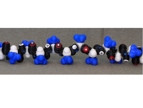
A Peppytide chain with eleven repeating units (an “11-mer”) is sufficiently long to explore the folding of various protein secondary structures. To build an 11-mer chain, you will need to 3D-print each of the three molecular subunits (M1-M3) as specified in Table 1, followed by machining and assembly. Here’s what the final product will look like.

Peppytides
Drilling and assembly blueprint

You can get these printed by an online 3D printing service, or print them yourself if you have access to a 3D printer. A shortcut would be to print all the parts using the same color in a single run. However, if you want to make the model more interesting and informative, it is more preferable to use 3 different colors for the three different types of parts. We have chosen black for the amide unit M1, white (ivory) for the alpha-carbon unit M2, and red/blue for the methyl-group unit M3. For ease of drilling and tapping of the alpha-carbon unit, you can also 3D-print one part holder M4. Similarly, for drilling the amide unit nitrogen atom and carbon atom magnet holes, you can 3D-print the respective holders M5 and M6. Lastly, you will need to 3D-print one helix template that also doubles as a stand M7. It helps to initiate the folding of an α-helix. Here is a link to download all the .STL files necessary.

Materials

Table 1: 3D-printed parts

Part Description Quantity

M1

Amide unit 3D-printed part(M1_amideUnit.stl) 12

M2

Alpha-carbon unit 3D-printed part(M2_alphacarbonUnit.stl) 11

M3

Methyl-group unit 3D-printed part(M3_methylGroupUnit.stl) 11

M4

Alpha-carbon unit-holder 3D-printed partTo hold the alpha carbon part in place during drilling and tapping(M4_alphacarbon_holder.stl) 1

M5

Amide-unit-holder nitrogen-atom 3D-printed partTo hold the amide part in place during drilling of the nitrogen atom magnet holes(M5_amideUnit_drillNitrogenAtom_holder.stl) 1

M6

Amide-unit-holder carbon-atom 3D-printed partTo hold the amide part in place during drilling of the carbon atom magnet holes(M6_amideUnit_drillCarbonAtom_holder.stl) 1

M7

Helix stand and template 3D-printed partTo help fold an α-helix(M7_helixTemplate.stl) 1

Table 2: Readily obtainable parts

Part Description Quantity

M8

Neodymium rod magnets,3/16″D x 1/8″H For hydrogen bonding 27 (2 for each amide, 3 for helix template M10)

M9

Neodymium rod magnets1/8″D x 1/8″H For bond faces (4 for each alpha-carbon unit, and 5 for each amide unit)

M10

Screw(Pan-head machine screw 5/8″H, 4-40 thread) For bonds 33

M11

Nut(3/32″H, 0.25″D, 4-40 thread) For bonds 33

M12

Spacer(Nylon spacer; 0.25″D x 3/8″H) For bonds 33 (3 for each alpha-carbon unit)

M13

Epoxy (JB-weld) For gluing H-bond magnets to amide units; bought from local hardware store 1

Table 3: Our suppliers for the readily obtainable parts

Part

Supplier Part Number
Screw (M10) McMaster-Carr(mcmaster.com) 91735A109
Nut (M11) 91841A005
Spacer (M12) 94639A202
Magnet (for bond faces, 1/8″D x 1/8″H) (M9) Magcraft.com NSN0658
Magnet (for H-bond, 3/16″D x 1/8″H) (M8) K&J Magnetics, Inc.(kjmagnetics.com) D32-N52

The Peppytide model is an exact scale model where 1 Angstrom (10-10 meters) equals 0.368”. Thus, the model subunits are held at a precise distance from each other. It is therefore extremely important that the spacers, screws, nuts used are of the exact size described in Table 2. Any variation would result in deviation from the effective bond lengths, and you may not be able to ultimately fold the chain into a perfect helix after all the hard work of assembly.

Tools Needed:
• 3D printer (we used uPrint Plus)
• Drill press and a set of numbered drill bits
• Tapping tools (4-40 thread)

YouTube player

Project Steps

3D print the parts.

To 3D print the parts M1-M7 you will need the STL files provided. Print these parts in the required quantity (Table 1).

The amide and alpha-carbon units are printed with slightly undersized pilot holes for the magnets, and these need to be drilled out later (see steps #2c-d and 3a-b).

To dissolve the supporting materials used during 3D-printing, immerse the parts into the 3D-printer’s clean-station bath and let it soak for 6-8 hours. It is important to melt away all the supporting materials from inside these hollow parts. Then follow with rinsing and drying.

Amide unit preparation.

[(Left) The 4 atoms of the amide units (M1), (Middle) The hydrogen-bond formed from the attraction of two magnets.]

a. Installation of the H-bond magnets. Sand the bottom face of the H-bond magnets M8 (3/16″ x 1/8″) with 220 grit sandpaper to roughen the surfaces for effective adhesion. Next, glue the magnets onto the amides using Epoxy (JB-weld), such that the oxygen atom (O) has the North pole up, and the hydrogen atom (H) has the South pole up. Leave for 24 hours for setting and drying.

b. Labeling. Color-code the amide units with red-ring for oxygen (O), white-ring for hydrogen (H), and blue-dot for nitrogen atoms (N) in the amide units.

c. Drilling dihedral rotational barrier magnet holes. Enlarge the pilot holes for magnets in the carbon (C) and nitrogen (N) atoms by drilling to a depth of 0.074″ (drill size #31, 0.120″). This hole-depth will allow each magnet to protrude by ~0.051″ after the press-fitting of the magnets M9 in step #4. You may use M5 and M6 holders for ease of drilling. Make sure that the part is firmly inside the holder, by pressing in tightly. The drill-surface of the part will be level with that of the holder, if inserted correctly.

d. Drilling the bond holes. Enlarge the central bond holes in the carbon (C) and nitrogen (N) atoms by drilling to a depth of 0.345″ (drill size 0.250”). This hole-depth will allow the nylon bond spacer to protrude by 1/32″ after press-fitting of the bond linkages in step #7.

Alpha-carbon unit preparation.

a. Drilling the rotational barrier magnet holes. As with the amides, enlarge the pilot holes for the magnets by drilling to a depth of 0.074″ (drill size #31, 0.120″). This hole-depth will allow each magnet to protrude by 0.051″. The final bore diameter of 0.120” is intentionally undersized to allow a press-fit of the 1/8” diameter magnets. You may use holder M4 for ease of handling the part.

b. Drilling the bond holes. Drill to a depth of 0.300″ (drill size #43, 0.089″) on the 3 faces (N-face, C-face and the side-chain-face) of the alpha-carbon units. Guide holes are provided, by design.

c. Tapping the bond holes. After drilling the central bond holes, tap them with 4-40 threads to their full drilled depth.

Add the rotational barrier magnets to amide and alpha carbon units.

[Press-fitting magnets. (Left) amide unit M1; (Right) alpha carbon unit M2.]

Press fit the dihedral magnets M9 (1/8″ x 1/8″) into alpha carbon units (with North pole up) and in amide units (with South pole up) as far as they will go in. Each magnet will protrude by ~0.051″.

Bond linkage assembly.

[Assembled bonds and related parts that need to be linked per repeating monomer unit. (Left) Assembled bond, (Right) Parts and bonds.]

Assemble screws M10, nuts M11, and spacers M12 to create the bond linkages. There are 3 such bonds per monomer unit: alpha carbon-to-amide(N), alpha carbon-to-amide (C), and alpha carbon-to-methyl group. Step #6 shows how to link the three bonds with the alpha carbon unit.

Alpha-carbon bond assembly.

[(Above) Alpha carbon unit with bond linkages.]

Assemble bonds into the alpha carbon units by screwing the bonds into the alpha carbon tapped holes (refer to step #3c) and securely tightening the nut, while leaving a slight gap (of about 0.01”) to allow free rotation of the spacer.

Backbone assembly.

[{Above) Connecting the alpha carbon unit with the two faces of amide units.]

Press-fit bond linkages from alpha carbon units into amides. The bonds will bottom out into the amide bores. Make sure to connect the amide carbon atom with the alpha carbon face marked “C”. Similarly, connect the amide nitrogen atom with the alpha carbon face marked “N”. This is extremely important to get a correct L-amino acid representation, and for correct phi, psi bonds.

Assembly.

[(Above) Completed backbone assembly of the Peppytide model.]

Repeat steps 6 and 7 to make the entire backbone chain of alternating amide unit and alpha-carbon unit.

Adding side chain residues.

[(Above) Addition of the side chain methyl units (red).]

Lastly, press-fit the methyl group units onto the 3rd bond linkages of the alpha carbon units in the backbone chain.

Step 9 gives the final assembled Peppytides chain.

Adding H-bond magnets to the helix template.

As in step #2-a, sand three H-bond magnets M8 (3/16″ x 1/8″) and glue them onto the helix template M7 using Epoxy (JB-weld) with South poles up. These represent the hydrogen atoms (H) that will initiate and stabilize the alpha helix fold in Peppytide. Leave for 24 hours for setting and drying.

The 11-mer polypeptide chain is now ready for experimenting with folding into the alpha-helices and beta sheets. Go to the Peppytides website for directions on how to fold. You would now need the helix stand from step #10 to help in folding. Here are what a folded alpha-helix and a folded beta-sheet look like.