The MintDuino kit is a fantastic project to help you learn the basic circuitry of an Arduino clone, but it is not mechanically sturdy enough for most projects. This breadboard-to-perfboard project will provide a solution to make your MintDuino as strong as the tin it comes in! Plus, this board layout even allows a 9V battery to fit in the tin alongside the perfboard MintDuino.

DSC_0939

Project Steps

Build Preparation & Things to Consider

Experience building the breadboard MintDuino is not necessary, but it might help you appreciate the board layout. This project mimics the build steps of the original MintDuino kit. If you need more explanation of the circuit, check out the original MintDuino project.

Not all perfboards are electrically identical to breadboards. Electrically connected holes on a board are often called strips. All sorts of names exist for different overall board layout of strips, but you do not need to learn them. All you really need to do is look at your perfboard and determine if it has any strips or not. If it has strips, such as the board in this project, then look to determine how similar or dissimilar the component layout will be given the strip orientation. Planning ahead is your best tactic in doing a new layout!

Note: the perfboard in this build is not identical to a breadboard i.e. the connected strips exist, but they are electrically different in layout.

Power Regulation: 9V to 5V

The first sub-circuit to layout and solder handles voltage regulation and the power LED indicator.

Gather the 7805 voltage regulator, two 10uF capacitors, a red LED, and wire.

Voltage regulator and Capacitor

Place the voltage regulator at the very top of your perfboard and solder the three leads. For the board to fit in the tin, you need to adjust the regulator to have the leads slightly exposed enough to bend down parallel with the board.

Place one 10uF capacitor adjacent to the voltage regulator. This component is polarized, which means the leads must be placed properly or the circuit will not function. The white stripe on the barrel of the capacitor in the image indicates the negative lead.

Another Capacitor and Layout Planning

Place the second 10uF capacitor (seen behind the voltage regulator). We will use the center two rails, the “power rail,” which are connected lengthwise. You might not be thinking yet about layout design, but it’s important that you consider it.

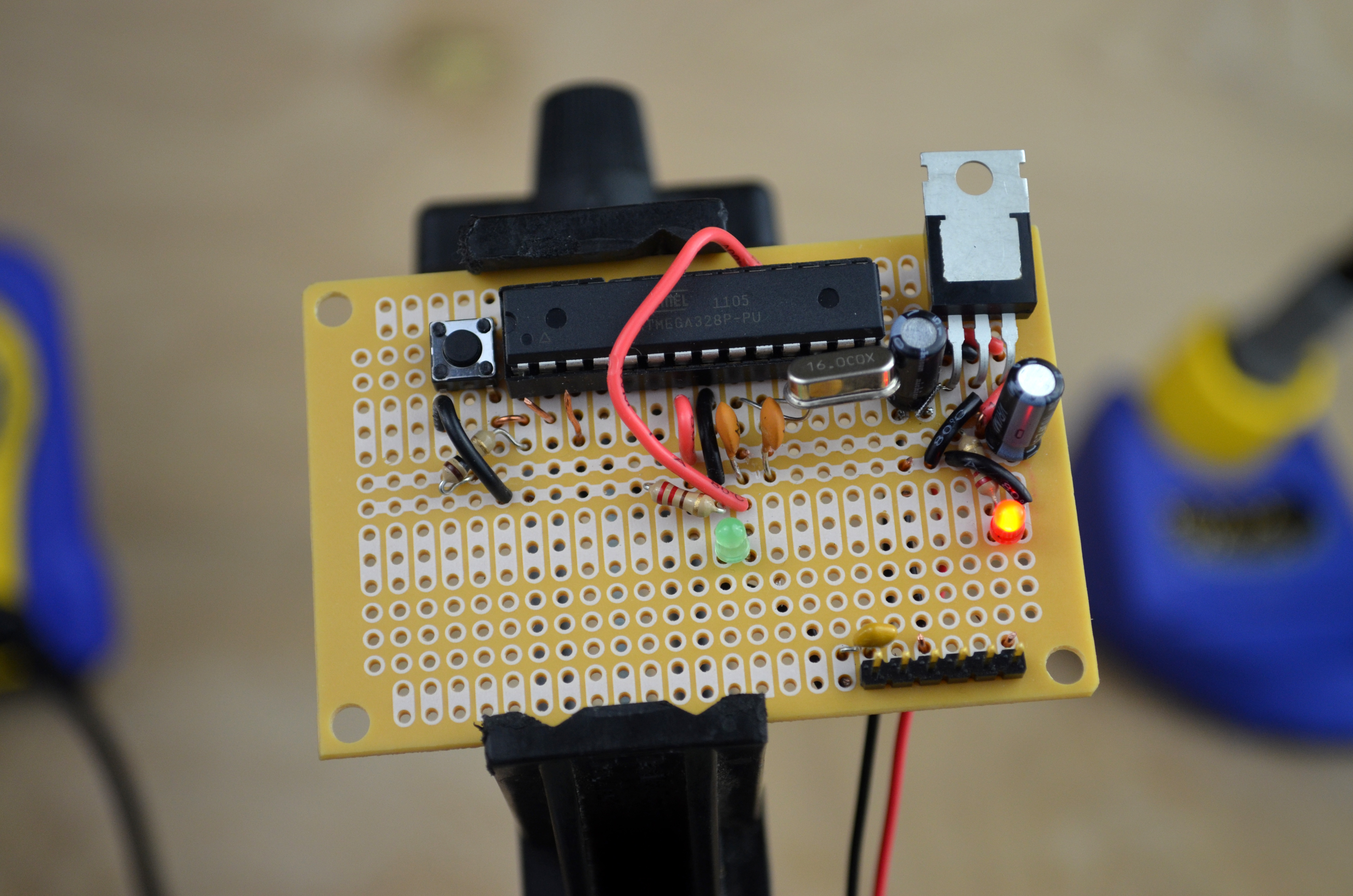
Traditional component layout would place the IC centered on the board and surround the chip with support peripherals, such as the power regulation circuit we are building now. Traditions are great to know, but spanning a 28-pin IC over the only two rails of contiguous lengthwise connection is problematic for adding in more components later.

Not having the IC in the center of the perfboard is the first big component layout decision that effects the layout. Since all components in a layout influence each other, 28-pins is a lot of influence!

Note: Placing the IC off-center will also allow room for the 9V battery inside the tin, as mentioned in the introduction.

Red LED

The red LED illuminates when power is properly distributed through the circuit.

Some LEDs will rest flush against the perfboard, but this tiny 5mm LED just does not. Use masking tape to affix the part while you solder it into position.

The LED requires power and ground to function. Connect a red wire to the positive terminal of the LED and the power rail. Take a 220Ω resistor and solder that between the negative terminal of the LED and the ground rail of the perfboard. Remember we decided that power and ground are the two adjacent rails that run lengthwise when the board is oriented in “portrait.”

9V Battery Clip

We don’t want to connect the 9V battery clip directly to the power and ground rails of the circuit. Instead, we need to have the power regulated and “smoothed” by the circuit. Masking tape is again helpful to position the wires while you solder.

The black wire of the battery clip connects to the negative rail of the capacitor (remember, negative connects to negative). Compare your layout with image two and solder in place.

The red wire of the battery clip connects to the positive rail of the capacitor. Before you solder the wire double-check that the wires are not tangled.

Testing the Circuit

Plug a 9V battery into the clip. Once connected the red LED will illuminate.

If the LED does not illuminate or flickers, quickly disconnect the battery and check your soldering for bad joints.

Congratulations! You just built a 5V regulated power supply.

Integrated Circuit Socket

Integrated Circuits (IC) such as the ATmega328P can be directly soldered to a perfboard, but if you fry the chip, there is not a simple fix. Thankfully IC sockets exist! The socket is soldered to the perfboard and the IC snaps into the socket.

Though the MintDuino does not come with any IC sockets, they are cheap and well worth tracking down. If you cannot find the right pin number at a local supplier, no worries! You can actually combine multiple IC sockets by simply placing them in adjoining holes.

Make your life easier and temporarily secure the IC socket to the perfboard while you solder it in place.

Integrated Circuit

Install the ATmega328P into the IC socket. Notice the perfboard has been rotated 180° and a sticker from the Maker’s Notebook applied to the IC for helpful reference.

Crystal & Capacitors

The crystal is non-polarized, so the orientation does not matter. What matters, however, is that the crystal connects to pin 9 and 10 of the ATmega.

Pin numbering can be tricky. Image two depicts the ATmega328P and two different numbers of the chip. The left illustration shows pin numbering according to the manufacturing data sheet. On the right illustration the pin numbering corresponds to the Arduino nomenclature.

Add two 22pF capacitors. One leg of the capacitor connects to a crystal leg, the other connects to ground. This is done twice; once for each leg of the crystal (image 3).

ATmega328P Power & Ground Take One

Cut a small black wire and use it to connect ATmega pin 8 and the ground rail.

Cut a small red wire and use it to connect ATmega pin 7 and the power rail.

If you forget which rail is power and which is ground look at the capacitor on the power rail. On the capacitor housing should be a stripe which indicates the negative side of the component.

ATmega328P Power & Ground Take Two

The ATmega requires three additional power-related connections: one for ground connecting pin 22 to the ground rail (image 1) and two for power connecting pins 20 and 21 each to the power rail (images 2 & 3).

Rather than route long wires for power and ground over the ATmega, this layout routes the wires on the underside of the perfboard.

This underside wiring approach demonstrates one method to reduce wire-clutter on your perfboard, but is not particularly easy to solder. On scrap perfboard attempt soldering a couple of wires to improve your technique — I should have done this too!

LED for Blink Sketch (Optional)

220Ω resistor: connect one lead to the ground rail and the other to the negative lead of the green LED.

Cut a long wire to connect one end to pin 19 on the ATmega and the other to the positive lead on the LED.

Remember pin 19 is the datasheet number; using Arduino nomenclature you are connecting this wire to digital pin 13. If this is confusing, consult step 10.

This step is completely optional and the components are not necessary for the MintDuino to function. Rather, these components physically express the blink sketch that is pre-loaded on the kit’s ATmega.

Reset Button

Solder the reset button so it spans the perfboard in the same manner as the IC-socket. Do this — and all soldering — while the power is not connected.

Wire one of the button terminals to ground with a black wire (image 2, rotated).

Nestled under the reset button’s black wire is a 10kΩ resistor (brown, black, orange) connecting pin 1 and the power rail.

FTDI

Unlike Rev. 3 Arduino UNO boards, the MintDuino does not have an FTDI chip onboard. Instead, the MintDuino breaks out a connection where you attach an FTDI Friend.

Connect the breakout pins (a strip of six header pins) and then brace yourself for more under-board soldering!

Solder the six breakout pins.

FTDI Wiring

Notice the upper-right corner of the board in the first image. The black wire connects the sixth pin of the FTDI breakout to the ground rail. The board in these images is oriented so that both the ATmega and the FTDI cable number from left to right.

Cut a long black wire and connect this from pin 1 of the ATmega to a hole adjacent to the FTDI breakout pins (image 2).

Cut two more black wires. One wire connects pin 2 on the ATmega to pin 3 of the FTDI header pins (image 3).

The second black wire you cut connects pin 3 on the ATmega to pin 2 of the FTDI (also image 3).

FTDI and a Capacitor

Remember the long black wire attached from pin 1 of the ATmega to the hole adjacent to the FTDI breakout? Place the 100nF capacitor so it connects this black wire to pin 1 of the FTDI. The first image shows the long legs of the capacitor from the underside of the perfboard.